K120 CVT PARK / NEUTRAL POSITION SWITCH INSTALLATION
PROCEDURE

 84540
1.INSTALL PARK/NEUTRAL POSITION SWITCH ASSEMBLY
Temporarily install the park/neutral position switch assembly to the transaxle case sub-assembly with the 2 bolts.
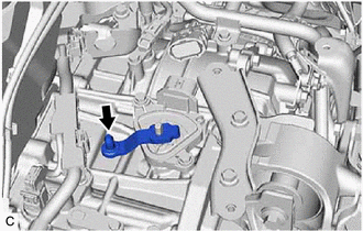
Temporarily install the transmission control shaft lever to the manual valve lever shaft.
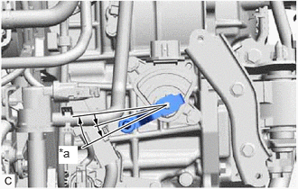
| *a | N |
Turn the transmission control shaft lever clockwise until it stops, then turn it counterclockwise 2 notches.
- NOTICE:
-
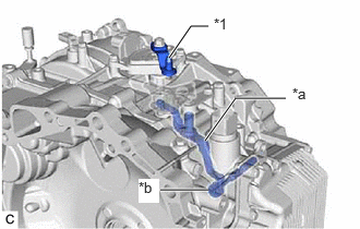 1.615,0.552 1.823,0.25 1.823,0.25 1.99,0.25 true 1.958,1.344 2.25,0.938 2.25,0.938 2.729,0.938 true 1.531,1.813 1.99,1.813 true 2.042,0.146 2.323,0.385 0.281,0.24 10 false *1 2.792,0.813 3.073,1.052 0.281,0.24 10 false *a 1.323,1.708 1.521,1.938 0.198,0.229 10 true *b
*1 Transmission Control Shaft Lever *a Manual Valve Link Lever Sub-assembly *b Manual Valve
-
If the transmission control shaft lever is turned counterclockwise more than necessary, manual valve link lever sub-assembly may separate from the manual valve.
Remove the transmission control shaft lever from the manual valve lever shaft.
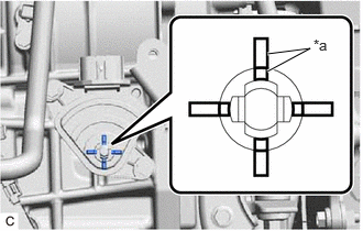
| *a | Protrusion |
Align the protrusions of the park/neutral position switch assembly as shown in the illustration.
Hold the park/neutral position switch assembly in that position and tighten the 2 bolts.
- Torque:
- 5.4 N*m (55 kgf*cm, 48 in.*lbf)
Install the transmission control shaft lever to the manual valve lever shaft with the washer and nut.
- Torque:
- 12.7 N*m (130 kgf*cm, 9 ft.*lbf)
- NOTICE:
-
Be careful of the direction of the transmission control shaft lever.
Connect the park/neutral position switch connector.
33820B
2.CONNECT TRANSMISSION CONTROL CABLE ASSEMBLY
- NOTICE:
-
Before connecting the transmission control cable assembly, check that the shift lever is in N.
| *a | N |
Turn the transmission control shaft lever clockwise until it stops, then turn it counterclockwise 2 notches.
- NOTICE:
-
1.615,0.552 1.823,0.25 1.823,0.25 1.99,0.25 true 1.958,1.344 2.25,0.938 2.25,0.938 2.729,0.938 true 1.531,1.813 1.99,1.813 true 2.042,0.146 2.323,0.385 0.281,0.24 10 false *1 2.792,0.813 3.073,1.052 0.281,0.24 10 false *a 1.323,1.708 1.521,1.938 0.198,0.229 10 true *b
*1 Transmission Control Shaft Lever *a Manual Valve Link Lever Sub-assembly *b Manual Valve
-
If the transmission control shaft lever is turned counterclockwise more than necessary, manual valve link lever sub-assembly may separate from the manual valve.
Connect the transmission control cable assembly to the No. 1 transmission control cable bracket with a new clip.
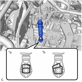
| *a | Correct |
| *b | Incorrect |
Connect the transmission control cable assembly to the transmission control shaft lever as shown in the illustration.
74404A
3.INSTALL BATTERY CLAMP SUB-ASSEMBLY
89661
4.INSTALL ECM
5.INSTALL BATTERY
6.INSPECT SHIFT LEVER POSITION
7.ADJUST SHIFT LEVER POSITION
84540
8.INSPECT PARK/NEUTRAL POSITION SWITCH ASSEMBLY
84540
9.ADJUST PARK/NEUTRAL POSITION SWITCH ASSEMBLY