SUPPLEMENTAL RESTRAINT SYSTEMS CENTER AIRBAG SENSOR ASSEMBLY INSTALLATION
CAUTION / NOTICE / HINT
- HINT:
- ·
Use the same procedure for RHD and LHD vehicles.
·The following procedure is for an LHD vehicle.
PROCEDURE

 89170
1.INSTALL AIRBAG SENSOR ASSEMBLY
Check that the power switch is off.
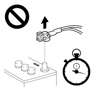
Check that the cable is disconnected from the negative (-) auxiliary battery terminal.
- CAUTION:
-
-
Wait at least 90 seconds after disconnecting the cable from the negative (-) auxiliary battery terminal to disable the SRS system.
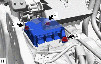
Install the airbag sensor assembly with the 3 bolts.
- Torque:
- 17.5 N*m (178 kgf*cm, 13 ft.*lbf)
- NOTICE:
- ·
Temporarily tighten the 2 bolts in the order of (A), (B) and then fully tighten the 3 bolts in the order of (C), (A) and (B).
·If the airbag sensor assembly has been dropped, or there are any cracks, dents or other defects in the case or connector, replace it with a new one.
·When installing the airbag sensor assembly, make sure that the SRS wiring does not interfere with or is not pinched between other parts.
·When the power switch is first turned to on (IG) after the airbag sensor assembly has been replaced, make sure that no one is in the vehicle.
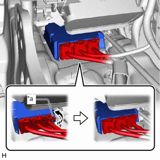
| *a | Lock Lever |

|
Move in this Direction |
Temporarily connect the connector and then move the lock lever in the direction indicated by the arrow to securely connect the connectors.
- NOTICE:
-
When connecting any airbag connector, take care not to damage the airbag wire harness.
Check that there is no looseness in the installed parts of the airbag sensor assembly.
58861B
2.INSTALL NO. 1 CONSOLE BOX DUCT
|
|
Install in this Direction |
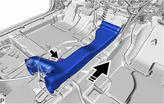
Install the No. 1 console box duct with the clip as shown in the illustration.
58510D
3.INSTALL FRONT FLOOR CARPET ASSEMBLY
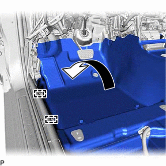
Install the front floor carpet assembly to its original position as shown in the illustration.
Engage the 2 guides.
Install the 2 front floor carpet clips.
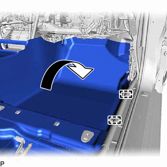
Install the front floor carpet assembly to its original position as shown in the illustration.
Engage the 2 guides.
for LHD:
Install the 2 front floor carpet clips.
for RHD:
Install the front floor carpet clip.
58569D
4.INSTALL FRONT FLOOR CAUTION PLATE COVER
78111
5.INSTALL ACCELERATOR PEDAL
78118
6.INSTALL ACCELERATOR PEDAL PAD
55606
7.INSTALL NO. 1 INSTRUMENT PANEL UNDER COVER SUB-ASSEMBLY (for LHD)
55606
8.INSTALL NO. 1 INSTRUMENT PANEL UNDER COVER SUB-ASSEMBLY (for RHD)
62414A
9.INSTALL LOWER CENTER PILLAR GARNISH LH
62332A
10.CONNECT REAR DOOR OPENING TRIM WEATHERSTRIP LH
67918A
11.INSTALL REAR DOOR SCUFF PLATE LH
62312B
12.CONNECT FRONT DOOR OPENING TRIM WEATHERSTRIP LH
62112A
13.INSTALL COWL SIDE TRIM SUB-ASSEMBLY LH
67914
14.INSTALL FRONT DOOR SCUFF PLATE LH
55607
15.INSTALL NO. 2 INSTRUMENT PANEL UNDER COVER SUB-ASSEMBLY
62413A
16.INSTALL LOWER CENTER PILLAR GARNISH RH
- HINT:
-
Use the same procedure as for the LH side.
-
Click hereVehicle Interior>INTERIOR PANELS / TRIM>ROOF HEADLINING>INSTALLATION
62331A
17.CONNECT REAR DOOR OPENING TRIM WEATHERSTRIP RH
67917A
18.INSTALL REAR DOOR SCUFF PLATE RH
- HINT:
-
Use the same procedure as for the LH side.
-
Click hereVehicle Interior>INTERIOR PANELS / TRIM>ROOF HEADLINING>INSTALLATION
62311B
19.CONNECT FRONT DOOR OPENING TRIM WEATHERSTRIP RH
62111A
20.INSTALL COWL SIDE TRIM SUB-ASSEMBLY RH
- HINT:
-
Use the same procedure as for the LH side.
-
Click hereVehicle Interior>INTERIOR PANELS / TRIM>ROOF HEADLINING>INSTALLATION
67913
21.INSTALL FRONT DOOR SCUFF PLATE RH
- HINT:
-
Use the same procedure as for the LH side.
-
Click hereVehicle Interior>INTERIOR PANELS / TRIM>ROOF HEADLINING>INSTALLATION
58810J
22.INSTALL CONSOLE BOX ASSEMBLY
23.INSTALL FRONT SEAT ASSEMBLY LH
24.INSTALL FRONT SEAT ASSEMBLY RH (for Power Seat)
- HINT:
-
Use the same procedure as for the LH side.
-
Click hereVehicle Interior>SEAT>FRONT SEAT ASSEMBLY (for Power Seat)>INSTALLATION
25.INSTALL FRONT SEAT ASSEMBLY RH (for Manual Seat)
26. PERFORM DIAGNOSTIC SYSTEM CHECK
27. PERFORM YAW RATE AND ACCELERATION SENSOR ZERO POINT CALIBRATION
When the airbag sensor assembly is replaced, perform zero point learning for the yaw rate and acceleration sensor.
Click hereBrake>BRAKE CONTROL / DYNAMIC CONTROL SYSTEMS>ELECTRONICALLY CONTROLLED BRAKE SYSTEM>CALIBRATION
- HINT:
-
The yaw rate and acceleration sensor is built into the airbag sensor assembly.