LIGHTING (EXT) HEADLIGHT ASSEMBLY(for LED Type Turn Signal Light) REMOVAL
CAUTION / NOTICE / HINT
The necessary procedures (adjustment, calibration, initialization or registration) that must be performed after parts are removed and installed, or replaced during headlight assembly removal/installation are shown below.
| Replaced Part or Performed Procedure | Necessary Procedure | Effect/Inoperative Function When Necessary Procedures are not Performed | Link |
|---|---|---|---|
|
*: Applies only for when removing and installing or replacing the rear television camera assembly. |
|||
| Headlight ECU sub-assembly LH | ·
Synchronize the vehicle information ·
Perform headlight ECU sub-assembly LH initialization |
Lighting System (EXT) (w/ Automatic Headlight Beam Level Control System) | ( ) |
| Front bumper assembly (w/ Parking Support Brake System) | ·
Measure ultrasonic sensor detection angle ·
Ultrasonic sensor detection angle registration |
Parking Support Brake System | ()
|
| Front bumper assembly (w/ Panoramic View Monitor System) | Front television camera view adjustment | Panoramic View Monitor System | ()
|
Replacement or removal and installation of 2 or more parts:
·
Front television camera assembly, front bumper assembly or radiator grille ·
Rear television camera assembly ·
Side television camera assembly LH or outer rear view mirror assembly LH ·
Side television camera assembly RH or outer rear view mirror assembly RH |
·
Television camera view adjustment ·
Rear television camera assembly optical axis (Back camera position setting)* |
||
- HINT:
- ·
Use the same procedure for the RH side and LH side.
·The following procedure is for the LH side.
PROCEDURE

 1.REMOVE FRONT BUMPER ASSEMBLY
2.REMOVE HEADLIGHT ASSEMBLY
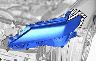

|
Protective Tape |
Apply protective tape around the headlight assembly as shown in the illustration.
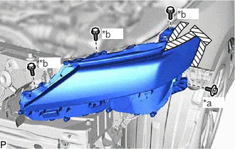
| *a | Bolt |
| *b | Screw |
Remove the bolt and 3 screws.
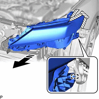

|
Separate in this Direction |
Disengage the guide to separate the headlight assembly as shown in the illustration.
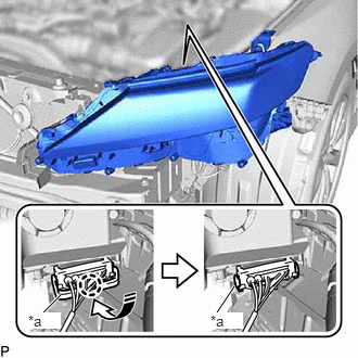
| *a | Connector Lock Lever |
|
|
Disengage in this Direction |
Disengage the claw, pull down the connector lock lever as shown in the illustration and disconnect the connector to remove the headlight assembly.