PARKING BRAKE ELECTRIC PARKING BRAKE SYSTEM C060E19 Left Electric Parking Brake Actuator Circuit Current Above Threshold
DESCRIPTION
| DTC No. | Detection Item | DTC Detection Condition | Trouble Area | Memory | Note |
|---|---|---|---|---|---|
| C060E19 | Left Electric Parking Brake Actuator Circuit Current Above Threshold | When the electric parking brake is operating, overcurrent is detected in the parking brake actuator assembly LH 3 times | ·
Parking brake actuator assembly LH ·
No. 2 parking brake wire assembly ·
Wire harness and connector ·
Parking brake ECU (brake actuator assembly) |
DTC stored | An electric parking brake system malfunction is displayed on the combination meter assembly. |
WIRING DIAGRAM
PROCEDURE
Make sure that there is no looseness at the locking part and the connecting part of the connectors.
- OK:
The connector is securely connected.
Disconnect the vR2 and v1 No. 2 parking brake wire assembly connectors.
Check both the connector case and the terminals for deformation and corrosion.
- OK:
No deformation or corrosion.
Measure the resistance according to the value(s) in the table below.
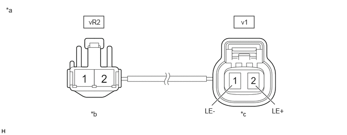
| *a | Front view of No. 2 Parking Brake Wire Assembly | *b | (to wire harness connector) |
| *c | (to Parking Brake Actuator Assembly LH) | - | - |
- Standard Resistance:
Tester Connection Condition Specified Condition vR2-2 - v1-2 (LE+) Always Below 1 Ω vR2-2 or v1-2 (LE+) - Body ground and other terminals Always 10 kΩ or higher vR2-1 - v1-1 (LE-) Always Below 1 Ω vR2-1 or v1-1 (LE-) - Body ground and other terminals Always 10 kΩ or higher
- Result:
Proceed to OK NG
OK
NG
Make sure the No. 2 parking brake wire assembly is securely installed.
Disconnect the A44 parking brake ECU (brake actuator assembly) connector.
Disconnect the v1 parking brake actuator assembly LH connector.
Measure the resistance according to the value(s) in the table below.
- Standard Resistance:
Tester Connection Condition Specified Condition A44-7 (MRL+) - v1-2 (LE+) Always Below 1 Ω A44-7 (MRL+) or v1-2 (LE+) - Body ground Always 10 kΩ or higher A44-8 (MRL-) - v1-1 (LE-) Always Below 1 Ω A44-8 (MRL-) or v1-1 (LE-) - Body ground Always 10 kΩ or higher
- Result:
Proceed to OK NG
OK
NG
OK
NG
Turn the power switch off.
Make sure the No. 2 parking brake wire assembly is securely installed.
Disconnect the v1 parking brake actuator assembly LH connector.
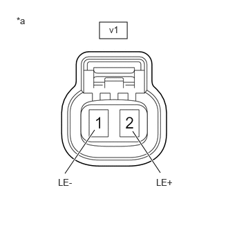
| *a | Front view of No. 2 Parking Brake Wire Assembly
(to Parking Brake Actuator Assembly LH) |
Measure the voltage according to the value(s) in the table below.
- Standard Voltage:
Tester Connection Condition Specified Condition v1-2 (LE+) - v1-1 (LE-) Electric parking brake not operating Below 1 V
- Result:
Proceed to OK NG
OK
NG
Disconnect the vR2 No. 2 parking brake wire assembly connector.
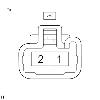
| *a | Front view of wire harness connector
(to No. 2 Parking Brake Wire Assembly) |
Measure the voltage according to the value(s) in the table below.
- Standard Voltage:
Tester Connection Condition Specified Condition vR2-2 - vR2-1 Electric parking brake not operating Below 1 V
- Result:
Proceed to OK NG
OK
NG
Disconnect the vR2 No. 2 parking brake wire assembly connector.
Disconnect the A44 parking brake ECU (brake actuator assembly) connector.
Measure the voltage according to the value(s) in the table below.
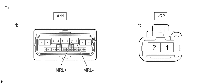
| *a | Front view of wire harness connector | *b | (to Parking Brake ECU (Brake Actuator Assembly)) |
| *c | (to No. 2 Parking Brake Wire Assembly) | - | - |
- Standard Voltage:
Tester Connection Condition Specified Condition vR2-2 or A44-7 (MRL+) - Body ground Always Below 1 V vR2-1 or A44-8 (MRL-) - Body ground Always Below 1 V
- Result:
Proceed to OK NG
OK
for LHD: Click hereBrake>BRAKE CONTROL / DYNAMIC CONTROL SYSTEMS>BRAKE ACTUATOR (for LHD)>REMOVAL
for RHD: Click hereBrake>BRAKE CONTROL / DYNAMIC CONTROL SYSTEMS>BRAKE ACTUATOR(for RHD)>REMOVAL
NG