EXTERIOR PANELS / TRIM REAR DOOR BELT MOULDING REMOVAL
CAUTION / NOTICE / HINT
The necessary procedures (adjustment, calibration, initialization, or registration) that must be performed after parts are removed and installed, or replaced during rear door belt moulding removal/installation are shown below.
| Replaced Part or Performed Procedure | Necessary Procedure | Effect/Inoperative Function When Necessary Procedures are not Performed | Link |
|---|---|---|---|
| Disconnect cable from negative auxiliary battery terminal | Perform steering sensor zero point calibration | Lane Tracing Assist System | ( ) |
| Pre-collision System | |||
| Memorize steering angle neutral point | Parking Assist Monitor System | ()
|
|
| Panoramic View Monitor System | ()
|
||
·
Rear door glass sub-assembly ·
Rear door glass run |
Initialize power window control system | ·
Auto up and down function ·
Jam protection function ·
Remote control function ·
Key-linked function ·
Wireless transmitter-linked function ·
Key-off operation function ·
Catch protection function ·
Window open warning function |
()
|
- HINT:
- ·
Use the same procedure for the RH side and LH side.
·The following procedure is for the LH side.
PROCEDURE

 1. PRECAUTION
- NOTICE:
-
After turning the power switch off, waiting time may be required before disconnecting the cable from the negative (-) auxiliary battery terminal. Therefore, make sure to read the disconnecting the cable from the negative (-) auxiliary battery terminal notices before proceeding with work.
-
Click hereGeneral>INTRODUCTION>REPAIR INSTRUCTION>PRECAUTION
64718C
2.REMOVE LUGGAGE TRIM SERVICE HOLE COVER
3.DISCONNECT CABLE FROM NEGATIVE AUXILIARY BATTERY TERMINAL
74038B
4.REMOVE REAR DOOR ARMREST COVER SUB-ASSEMBLY
5.REMOVE REAR POWER WINDOW REGULATOR SWITCH ASSEMBLY WITH REAR DOOR UPPER ARMREST BASE PANEL
74260
6.REMOVE REAR ARMREST ASSEMBLY
67604
7.REMOVE REAR DOOR TRIM BOARD SUB-ASSEMBLY
68174A
8.REMOVE REAR DOOR INNER GLASS WEATHERSTRIP
67844A
9.REMOVE REAR DOOR NO. 2 SERVICE HOLE COVER
67842E
10.REMOVE REAR DOOR SERVICE HOLE COVER
67848A
11.REMOVE REAR DOOR NO. 1 VENT SEAL
67858B
12.REMOVE REAR DOOR PANEL PROTECTOR
68152C
13.REMOVE REAR DOOR GLASS RUN
67872
14.DISCONNECT REAR DOOR WEATHERSTRIP
67408F
15.REMOVE REAR DOOR REAR LOWER WINDOW FRAME SUB-ASSEMBLY
68124B
16.REMOVE REAR DOOR QUARTER WINDOW GLASS
68104
17.REMOVE REAR DOOR GLASS SUB-ASSEMBLY
75740
18.REMOVE REAR DOOR BELT MOULDING ASSEMBLY
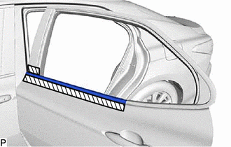

|
Protective Tape |
Apply protective tape around the rear door belt moulding assembly as shown in the illustration.
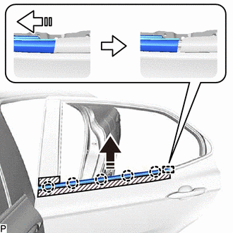

|
Remove in this Direction (1) |

|
Remove in this Direction (2) |
Disengage the 5 claws and guide to remove the rear door belt moulding assembly as shown in the illustration.