POWER DISTRIBUTION FUSIBLE LINK(for 120A DC/DC) INSTALLATION
PROCEDURE

 82620A
1.INSTALL FUSIBLE LINK BLOCK ASSEMBLY
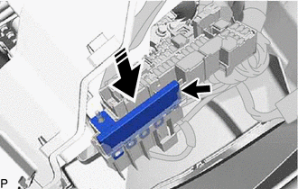

|
Install in this Direction |
Install the fusible link block assembly as shown in the illustration and connect the connector.
Connect the 4 wire harnesses with the 4 bolts.
- Torque:
- 5.4 N*m (55 kgf*cm, 48 in.*lbf)
Engage the 6 claws to connect the 3 connectors.
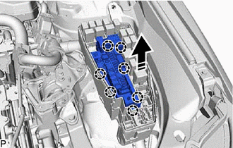
|
|
Install in this Direction |
Engage the 7 claws to install the fuse block assembly to the engine room relay block assembly as shown in the illustration.
82663
2.INSTALL RELAY BLOCK LOWER COVER
Engage the 9 claws to install the relay block lower cover.
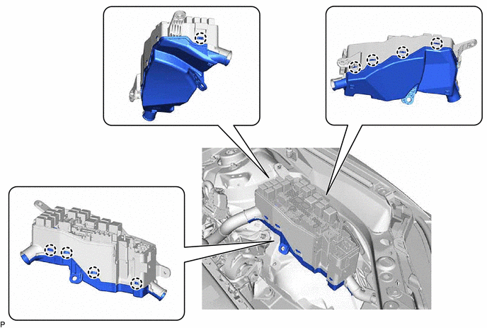
The vinyl tape (flame retardance) is wrapped as shown in the illustration.
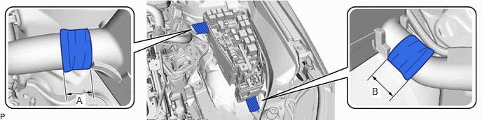
- Reference Measurement:
Area Measurement Area Measurement A 40 mm (1.57 in.) B 40 mm (1.57 in.)
Connect the wire harness with a new wiring harness clamp as shown in the illustration.
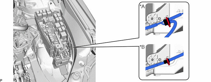
| *A | for LHD | *B | for RHD |

|
Positioning Tape | - | - |
Install the 2 bolts and nut.
- Torque:
- 8.0 N*m (82 kgf*cm, 71 in.*lbf)
Engage the claw to connect the wire harness.
Connect the 5 connectors.
Install the nut.
- Torque:
- 8.0 N*m (82 kgf*cm, 71 in.*lbf)
Engage the 2 claws and clamp to connect the wire harness.
82662B
3.INSTALL NO. 2 RELAY BLOCK COVER
Engage the 2 claws to install the No. 2 relay block cover.
89661
4.INSTALL ECM
5.INSTALL AIR CLEANER ASSEMBLY WITH AIR CLEANER HOSE
17750A
6.INSTALL INLET AIR CLEANER ASSEMBLY
53295E
7.INSTALL COOL AIR INTAKE DUCT SEAL
12601B
8.INSTALL NO. 1 ENGINE COVER SUB-ASSEMBLY
9.CONNECT CABLE TO NEGATIVE AUXILIARY BATTERY TERMINAL
64718C
10.INSTALL LUGGAGE TRIM SERVICE HOLE COVER