Home › Engine / Hybrid System › 1BZ-FPE (ENGINE CONTROL) › ELECTRONIC CONTROLLED CARBURETOR SYSTEM › 2017.01–2021.01
RM2850E _51 Engine / Hybrid System _073136 1BZ-FPE ENGINE CONTROL _0355837 ELECTRONIC CONTROLLED CARBURETOR SYSTEM J

1BZ-FPE ENGINE CONTROL  ELECTRONIC CONTROLLED CARBURETOR SYSTEM  Fuel Cut Solenoid Circuit  


DESCRIPTION

·

FUEL CUT CONTROL AT THE TIME OF DECELERATION

The catalytic converter temperature control and fuel ratio have been improved by stopping the computer signal to the fuel cut solenoid valve and cutting off slow fuel when decelerating with the engine speed at more than fuel cut off speed.

The computer signal to the solenoid valve is resumed with the engine speed at less than fuel return speed or the idling contact point OFF.

When the engine coolant temperature is low, fuel cut off speed and fuel return speed increase.

·

AIR FUEL RATIO CONTROL AT THE START OF OPERATION

In order to prevent air fuel ratio from becoming too rich at the start of operation, duty ratio control operates when the starter signal is input into the computer.


WIRING DIAGRAM
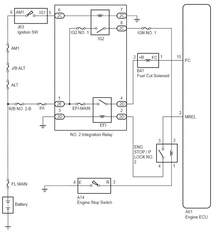
A403043E01
0.344,0.323 0.542,0.573 0.198,0.25 10 false 6 0.531,0.323 0.875,0.51 0.344,0.188 10 false AM1 1.313,0.333 1.604,0.563 0.292,0.229 10 false IG1 1.635,0.333 1.833,0.583 0.198,0.25 10 false 5 1.948,0.25 2.146,0.5 0.198,0.25 10 false 6 1.917,0.438 2.219,0.688 0.302,0.25 10 false 2C 0.583,0.813 0.938,1.021 0.354,0.208 10 false J63 0.583,0.99 1.458,1.24 0.875,0.25 10 false Ignition SW 0.375,1.531 0.792,1.76 0.417,0.229 10 false AM1 0.385,2.198 1.063,2.385 0.677,0.188 10 false J/B ALT 0.375,2.76 0.833,2.958 0.458,0.198 10 false ALT 0.292,3.552 1.146,3.76 0.854,0.208 10 false R/B NO. 2-B 1.323,3.542 1.635,3.781 0.313,0.24 10 false P/I 2.365,1 3.156,1.208 0.792,0.208 10 false IG2 NO. 1 3.271,1.208 3.615,1.427 0.344,0.219 10 false IG2 4.031,0.24 4.229,0.458 0.198,0.219 10 false 7 4,0.438 4.281,0.635 0.281,0.198 10 false 2C 4.031,0.677 4.229,0.927 0.198,0.25 10 false 8 3.99,0.865 4.271,1.094 0.281,0.229 10 false 2C 4.604,1.01 5.354,1.25 0.75,0.24 10 false IGN NO. 1 4.469,1.823 4.667,2.073 0.198,0.25 10 false 2 4.646,1.833 4.844,2.083 0.198,0.25 10 false +B 5.083,1.844 5.354,2.083 0.271,0.24 10 false FC 5.365,1.813 5.563,2.063 0.198,0.25 10 false 1 5.917,1.813 6.146,2.063 0.229,0.25 10 false 15 6.198,1.938 6.49,2.156 0.292,0.219 10 false FC 4.583,2.281 4.99,2.49 0.406,0.208 10 false B41 4.594,2.448 5.76,2.698 1.167,0.25 10 false Fuel Cut Solenoid 4.031,3.198 4.208,3.385 0.177,0.188 10 false 4 4,3.396 4.292,3.646 0.292,0.25 10 false 2D 4.031,3.615 4.229,3.802 0.198,0.188 10 false 2 3.99,3.823 4.26,4.042 0.271,0.219 10 false 2D 3.344,4.104 3.677,4.302 0.333,0.198 10 false EFI 2.427,3.542 3.219,3.771 0.792,0.229 10 false EFI-MAIN 1.948,3.198 2.146,3.448 0.198,0.25 10 false 1 1.906,3.396 2.177,3.625 0.271,0.229 10 false 2E 1.958,3.615 2.177,3.823 0.219,0.208 10 false 3 1.917,3.823 2.25,4.063 0.333,0.24 10 false 2D 2.354,4.417 3.865,4.646 1.51,0.229 10 false NO. 2 Integration Relay 4.49,4.833 5.167,5.531 0.677,0.698 10 false ENG STOP / P LOCK NO. 2 5.302,4.625 5.479,4.813 0.177,0.188 10 false 3 5.802,4.615 6,4.833 0.198,0.219 10 false 2 6,3.688 6.198,3.906 0.198,0.219 10 false 2 6.188,3.823 6.688,4.042 0.5,0.219 10 false MREL 0.385,6.073 1.115,6.313 0.729,0.24 10 false FL MAIN 0.5,6.75 1.26,7 0.76,0.25 10 false Battery 2.458,6.01 2.656,6.26 0.198,0.25 10 false 4 2.635,6.021 2.833,6.271 0.198,0.25 10 false E 2.583,6.521 2.979,6.708 0.396,0.188 10 false A14 2.583,6.688 3.979,6.927 1.396,0.24 10 false Engine Stop Switch 3.563,6.01 3.76,6.26 0.198,0.25 10 false R 3.781,6.01 3.969,6.188 0.188,0.177 10 false 3 6.208,7 6.563,7.198 0.354,0.198 10 false A51 6.208,7.177 7.021,7.406 0.813,0.229 10 false Engine ECU 5.302,5.469 5.5,5.719 0.198,0.25 10 false 4 5.792,5.469 5.99,5.635 0.198,0.167 10 false 1

CAUTION / NOTICE / HINT

NOTICE:

Inspect the fuses for circuits related to this system before performing the following procedure.


PROCEDURE
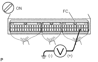
1.Check voltage between terminal FC of engine ECU connector and body ground.
A401603E01
2.802,1.052 2.417,0.427 true 0.563,0.208 0.875,0.406 0.313,0.198 10 false ON 2.208,0.313 2.521,0.51 0.313,0.198 10 false FC 1.698,1.875 2.01,2.073 0.313,0.198 10 false (-) 2.365,1.875 2.677,2.073 0.313,0.198 10 false (+)

PREPARATION:

a.

Remove the side trim bracket.


b.

Turn the ignition switch ON.


CHECK:

Measure voltage between terminal FC of the engine ECU and body ground.

OK:

Voltage: 9 - 14 V


Result:
Proceed to
OK
NG


OK

NG

2.Check fuel cut solenoid valve.
Result:
Proceed to
OK
NG


OK

3.Check EFI relay.

NG

Replace fuel cut solenoid valve.

3.Check EFI relay.

OK

4.Check engine stop switch.

NG

Replace EFI relay.

4.Check engine stop switch.
Result:
Proceed to
OK
NG


OK

5.Check ENG STOP/P LOCK NO. 2 relay.

NG

Repair engine stop switch.

5.Check ENG STOP/P LOCK NO. 2 relay.

OK

6.Check ignition switch.

NG

Repair ENG STOP/P LOCK NO. 2 relay.

6.Check ignition switch.

OK

7.Check for open and short in harness and connector fuel cut solenoid valve circuit

NG

Replace ignition switch.

7.Check for open and short in harness and connector fuel cut solenoid valve circuit

OK

NG

Repair or replace harness or connector.