Home › Engine / Hybrid System › 1BZ-FPE (ENGINE CONTROL) › ELECTRONIC CONTROLLED CARBURETOR SYSTEM › 2017.01–2021.01
RM2850E _51 Engine / Hybrid System _073136 1BZ-FPE ENGINE CONTROL _0355837 ELECTRONIC CONTROLLED CARBURETOR SYSTEM J

1BZ-FPE ENGINE CONTROL  ELECTRONIC CONTROLLED CARBURETOR SYSTEM  Idle Speed Control Valve System Malfunction  


DESCRIPTION
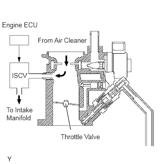
A403029E01
1.479,2.719 1.375,2.167 true 0.042,0.438 0.896,0.635 0.854,0.198 10 false Engine ECU 0.792,0.76 1.854,0.979 1.063,0.219 10 false From Air Cleaner 0.25,1.5 0.635,1.708 0.385,0.208 10 false ISCV 0.135,2.219 0.708,2.573 0.573,0.354 10 false To Intake Manifold 1.271,2.781 2.323,3 1.052,0.219 10 false Throttle Valve

The idle speed control valve is located on the carburetor and intake air bypassing the throttle valve is directed to the ISCV through a passage.

In this way the intake air volume bypassing the throttle valve is regulated, with the engine speed being controlled.

The engine ECU operates only the idle speed control valve to perform idle-up and provide feedback for the target idling speed.

WIRING DIAGRAM
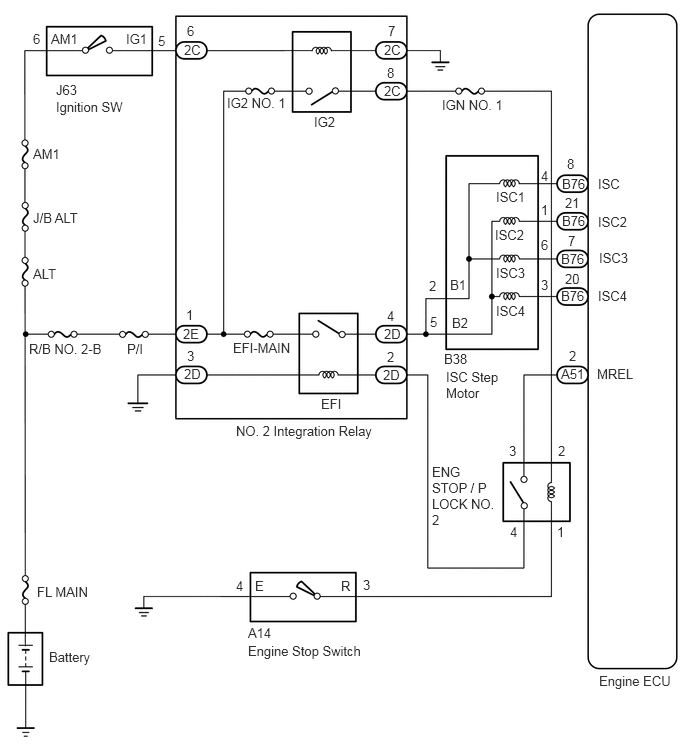
A403044E01
0.344,0.323 0.51,0.521 0.167,0.198 10 false 6 0.531,0.323 0.896,0.521 0.365,0.198 10 false AM1 1.313,0.323 1.656,0.552 0.344,0.229 10 false IG1 1.646,0.344 1.813,0.542 0.167,0.198 10 false 5 1.948,0.24 2.115,0.438 0.167,0.198 10 false 6 1.917,0.438 2.177,0.656 0.26,0.219 10 false 2C 0.583,0.854 0.938,1.083 0.354,0.229 10 false J63 0.583,1.031 1.51,1.26 0.927,0.229 10 false Ignition SW 0.344,1.521 0.75,1.719 0.406,0.198 10 false AM1 0.344,2.188 0.969,2.375 0.625,0.188 10 false J/B ALT 0.344,2.771 0.771,3 0.427,0.229 10 false ALT 0.302,3.552 1.167,3.781 0.865,0.229 10 false R/B NO. 2-B 1.323,3.552 1.646,3.802 0.323,0.25 10 false P/I 1.917,3.813 2.188,4.01 0.271,0.198 10 false 2D 1.948,3.625 2.115,3.823 0.167,0.198 10 false 3 1.906,3.396 2.24,3.604 0.333,0.208 10 false 2E 1.938,3.198 2.104,3.396 0.167,0.198 10 false 1 2.427,3.542 3.115,3.74 0.688,0.198 10 false EFI-MAIN 3.344,4.125 3.667,4.323 0.323,0.198 10 false EFI 2.458,4.406 3.938,4.677 1.479,0.271 10 false NO. 2 Integration Relay 3.99,3.823 4.25,4.031 0.26,0.208 10 false 2D 4.031,3.635 4.26,3.844 0.229,0.208 10 false 2 4,3.396 4.375,3.594 0.375,0.198 10 false 2D 4.031,3.208 4.198,3.406 0.167,0.198 10 false 4 2.365,0.99 3.083,1.208 0.719,0.219 10 false IG2 NO. 1 3.271,1.188 3.667,1.375 0.396,0.188 10 false IG2 4,0.865 4.313,1.073 0.313,0.208 10 false 2C 4.031,0.677 4.198,0.875 0.167,0.198 10 false 8 4,0.438 4.302,0.635 0.302,0.198 10 false 2C 4.042,0.24 4.208,0.438 0.167,0.198 10 false 7 4.604,1.01 5.333,1.208 0.729,0.198 10 false IGN NO. 1 5.167,1.969 5.563,2.188 0.396,0.219 10 false ISC1 5.156,2.365 5.552,2.594 0.396,0.229 10 false ISC2 5.167,2.76 5.542,2.969 0.375,0.208 10 false ISC3 5.167,3.156 5.531,3.344 0.365,0.188 10 false ISC4 4.688,2.885 4.917,3.083 0.229,0.198 10 false B1 4.708,3.281 5,3.479 0.292,0.198 10 false B2 4.469,2.896 4.656,3.083 0.188,0.188 10 false 2 4.479,3.271 4.646,3.469 0.167,0.198 10 false 5 5.635,1.75 5.802,1.948 0.167,0.198 10 false 4 5.635,2.104 5.802,2.302 0.167,0.198 10 false 1 5.635,2.469 5.802,2.667 0.167,0.198 10 false 6 5.635,2.885 5.802,3.083 0.167,0.198 10 false 3 5.844,3 6.208,3.208 0.365,0.208 10 false B76 5.885,2.823 6.104,3.021 0.219,0.198 10 false 20 5.844,2.615 6.208,2.823 0.365,0.208 10 false B76 5.917,2.427 6.083,2.625 0.167,0.198 10 false 7 5.854,2.219 6.219,2.427 0.365,0.208 10 false B76 5.885,2.031 6.104,2.229 0.219,0.198 10 false 21 5.854,1.833 6.135,2.031 0.281,0.198 10 false B76 5.906,1.625 6.073,1.823 0.167,0.198 10 false 8 6.229,1.833 6.542,2.031 0.313,0.198 10 false ISC 6.229,2.229 6.708,2.427 0.479,0.198 10 false ISC2 6.24,2.604 6.688,2.802 0.448,0.198 10 false ISC3 6.229,3 6.656,3.188 0.427,0.188 10 false ISC4 6.219,3.813 6.75,4.031 0.531,0.219 10 false MREL 5.927,3.625 6.094,3.823 0.167,0.198 10 false 2 5.844,3.813 6.177,4.01 0.333,0.198 10 false A51 4.625,3.656 5.01,3.865 0.385,0.208 10 false B38 4.646,3.844 5.219,4.177 0.573,0.333 10 false ISC Step Motor 0.385,6.083 1.26,6.271 0.875,0.188 10 false FL MAIN 0.51,6.76 1.177,7.021 0.667,0.26 10 false Battery 2.458,6.021 2.646,6.24 0.188,0.219 10 false 4 2.656,6.021 2.854,6.24 0.198,0.219 10 false E 3.552,6.021 3.813,6.219 0.26,0.198 10 false R 3.781,6.01 3.948,6.208 0.167,0.198 10 false 3 2.583,6.51 3.01,6.698 0.427,0.188 10 false A14 2.583,6.698 4.063,6.969 1.479,0.271 10 false Engine Stop Switch 6.24,7.01 7.021,7.24 0.781,0.229 10 false Engine ECU 5.313,5.458 5.479,5.656 0.167,0.198 10 false 4 5.802,5.458 5.969,5.656 0.167,0.198 10 false 1 5.813,4.615 5.979,4.813 0.167,0.198 10 false 2 5.302,4.615 5.469,4.813 0.167,0.198 10 false 3 4.5,4.833 5.177,5.531 0.677,0.698 10 false ENG STOP / P LOCK NO. 2

CAUTION / NOTICE / HINT

NOTICE:

Inspect the fuses for circuits related to this system before performing the following procedure.


HINT:

Read freeze frame data using hand-held tester. Because freeze frame records the engine conditions when the malfunction is detected, when troubleshooting it is useful for determining whether the vehicle was running or stopped, the engine warmed up or not, the air-fuel ratio lean or rich, etc. at the time of the malfunction.


PROCEDURE

1.Check operation of the ISC valve.

PREPARATION:

a.

Connect the hand-held tester to the DLC3.


b.

Turn ignition switch ON and hand-held tester main switch ON.


c.

Select the active test mode on the hand-held tester.


CHECK:

Check engine speed when the ISC valve operated by hand-held tester.

OK:

Engine speed is increased and decreased in response to change of ISC duty ratio.


Result:
Proceed to
OK
NG


OK

3.Check air induction system.

NG

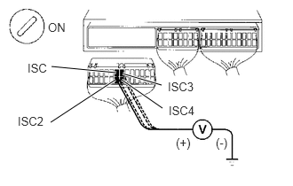
2.Check voltage between terminals ISC, ISC2, ISC3 and ISC4 of engine ECU connector and body ground.
A403030E01
0.604,0.781 1.365,0.854 true 0.594,1.438 1.354,0.938 true 1.438,0.865 1.896,1 true 1.427,0.938 1.906,1.271 true 0.563,0.24 0.875,0.438 0.313,0.198 10 false ON 0.323,0.719 0.635,0.917 0.313,0.198 10 false ISC 0.208,1.344 0.719,1.563 0.51,0.219 10 false ISC2 1.969,0.938 2.406,1.156 0.438,0.219 10 false ISC3 1.979,1.219 2.385,1.406 0.406,0.188 10 false ISC4 2.063,1.594 2.375,1.792 0.313,0.198 10 false (+) 2.531,1.594 2.844,1.792 0.313,0.198 10 false (-)

PREPARATION:

a.

Remove the side trim bracket.


b.

Disconnect the connector of engine ECU.


c.

Turn ignition switch ON.


CHECK:

Measure voltage between terminals ISC, ISC2, ISC3 and ISC4 of engine ECU connector and body ground.

OK:

Voltage: 9 - 14 V


Result:
Proceed to
OK
NG


OK

3.Check air induction system.

NG

4.Check ISC valve.
3.Check air induction system.
Result:
Proceed to
OK
NG


OK

NG

Repair or replace.

4.Check ISC valve.
Result:
Proceed to
OK
NG


OK

5.Check EFI relay.

NG

Replace ISC valve.

5.Check EFI relay.

OK

6.Check engine stop switch.

NG

Replace EFI relay.

6.Check engine stop switch.
Result:
Proceed to
OK
NG


OK

7.Check ENG STOP/P LOCK NO. 2 relay.

NG

Repair engine stop switch.

7.Check ENG STOP/P LOCK NO. 2 relay.

OK

8.Check ignition switch.

NG

Repair ENG STOP/P LOCK NO. 2 relay.

8.Check ignition switch.

OK

NG

Replace ignition switch.