A444E AUTOMATIC TRANSMISSION / TRANSAXLE AUTOMATIC TRANSMISSION ASSEMBLY INSTALLATION
PROCEDURE

 32000
1.INSTALL TORQUE CONVERTER CLUTCH ASSEMBLY
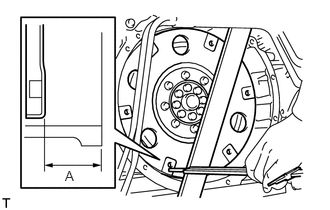
Clean the torque converter set bolt installation holes of the drive plate.
Using a vernier caliper and a straight edge, measure dimension A between the transmission and the end surface of the drive plate[*1 ].
- HINT:
-
Measure the thickness of the straight edge.
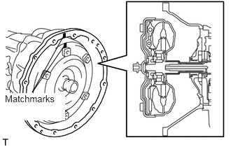
Aligning the matchmarks on the transmission case and torque converter, engage the splines of the input shaft and turbine runner.
- NOTICE:
-
Install the torque converter laterally to the input shaft.
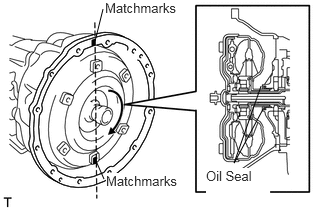
Engage the splines of the starter shaft and starter while turning the torque converter clockwise.
- NOTICE:
- ·
Turn the torque converter approximately 180°.
·Do not damage the oil seal.
·Install the torque converter laterally to the input shaft.
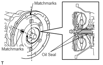
Turn the torque converter and align the matchmarks on the torque converter and transmission case to engage the key of the oil pump drive gear into the slot on the torque converter. Matchmarks
- NOTICE:
- ·
Turn the torque converter approximately 180°.
·Do not damage the oil seal.
·Install the torque converter laterally to the input shaft.
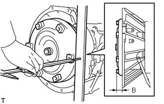
Using a vernier caliper and a straight edge, measure dimension B shown in the illustration and check that B is smaller than A measured in step[*1 ] .
- Standard:
A + 1 mm (0.04 in.) or less
- HINT:
-
Measure the thickness of the straight edge.
35000
2.INSTALL AUTOMATIC TRANSMISSION ASSEMBLY
Make sure that the 2 knock pins are on engine side.
Hold the engine and automatic transmission assembly horizontally and then engage the knock pins.
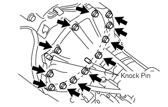
Install the automatic transmission assembly to the engine assembly with the12 bolts.
- Torque:
43 N*m (439 kgf*cm, 32 ft.*lbf)
- NOTICE:
- ·
Check whether the torque converter turns by hand.
·Be careful not to damage the knock pin.
12325
3.INSTALL NO.3 ENGINE MOUNTING BRACKET
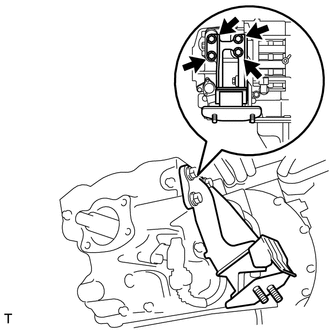
Install the No.3 engine mounting bracket to the automatic transmission assembly with the 4 bolts.
- Torque:
44 N*m (449 kgf*cm, 33 ft.*lbf)
12321
4.INSTALL NO.1 ENGINE MOUNTING BRACKET
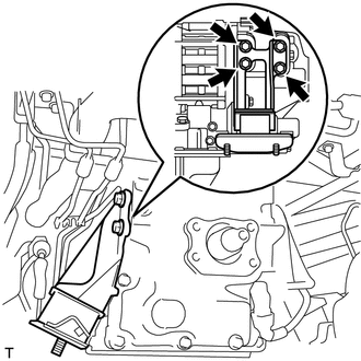
Install the No.1 engine mounting bracket to the automatic transmission assembly with the 4 bolts.
- Torque:
44 N*m (449 kgf*cm, 33 ft.*lbf)
51204
5.INSTALL NO.3 FRAME CROSSMEMBER SUB-ASSEMBLY
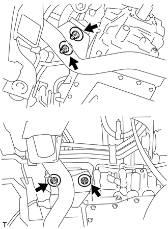
Install the No.3 frame crossmember sub-assembly to the No.3 engine mounting bracket and No.1engine mounting bracket with the 4 nuts and 4 washers.
- Torque:
56 N*m (571 kgf*cm, 41 ft.*lbf)
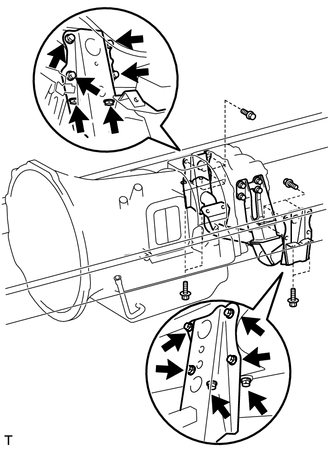
Install the No.3 frame crossmember sub-assembly with the 12 bolts.
- Torque:
50 N*m (510 kgf*cm, 37 ft.*lbf)
32101A
6.INSTALL DRIVE PLATE & TORQUE CONVERTER CLUTCH SETTING BOLT
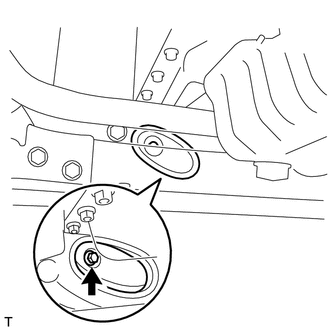
Clean the torque converter set bolts installation holes of the torque converter.
Clean the torque converter set bolts.
Apply adhesive 1324 on the six torque converter set bolts.
Install the 6 torque converter clutch setting bolts.
- Torque:
53 N*m (540 kgf*cm, 39 ft.*lbf)
- HINT:
- ·
First install the green-colored bolt and then the remaining 5 bolts.
·tighten the 6 set bolts equally.
11354
7.INSTALL FLYWHEEL HOUSING DUST SEAL
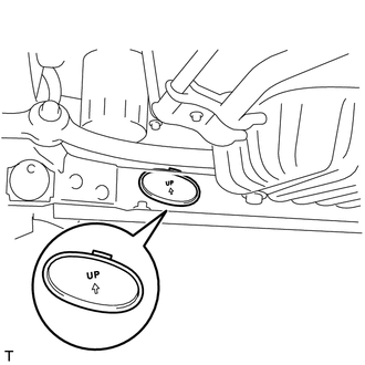
Install the flywheel housing dust seal to the automatic transmission assembly.
8.CONNECT CONNECTORS
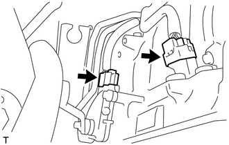
Connect the park/neutral position switch connector and transmission wire connector.
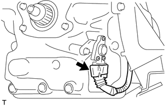
Connect the speedometer sensor connector.
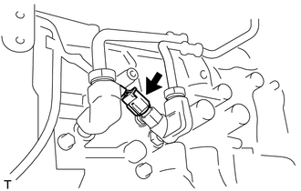
Connect the ATF temperature sensor connector.
35013
9.INSTALL TRANSMISSION OIL FILLER TUBE SUB-ASSEMBLY
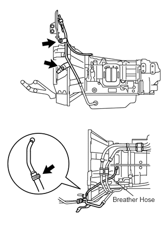
Coat a new O-ring with ATF, and install them to the transmission oil filler tube sub-assembly.
Install the transmission oil filler tube sub-assembly to the automatic transmission assembly with the 2 bolts.
- Torque:
12 N*m (122 kgf*cm, 9 ft.*lbf)
Connect the breather hose to the transmission oil filler tube sub-assembly.
Install the oil level gauge to the transmission oil filler tube sub-assembly.
33823
10.INSTALL NO.1 TRANSMISSION CONTROL CABLE BRACKET
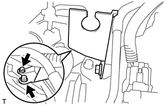
Install the No.1 transmission control cable bracket to the automatic transmission assembly with the 2 bolts.
- Torque:
14 N*m (143 kgf*cm, 10 ft.*lbf)
33820B
11.INSTALL TRANSMISSION CONTROL CABLE ASSEMBLY
32922
12.INSTALL NO.1 OIL COOLER OUTLET TUBE
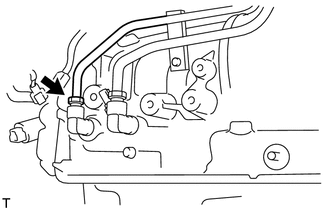
Install the No.1 oil cooler outlet tubu to the automatic transmission assembly.
- Torque:
69 N*m (704 kgf*cm, 51 ft.*lbf)
32921
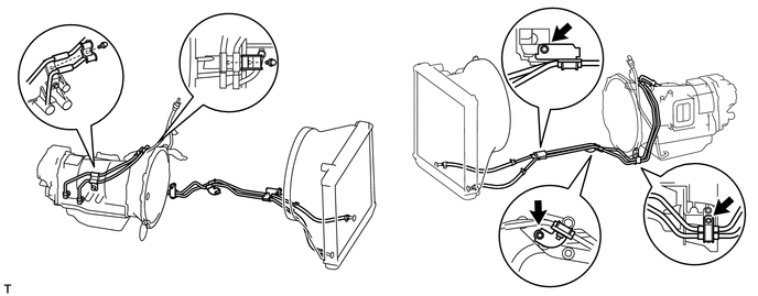
13.INSTALL NO.1 OIL COOLER INLET TUBE
Install the No.1 oil cooler inlet tube to the automatic transmission assembly.
- Torque:
69 N*m (704 kgf*cm, 51 ft.*lbf)
Install the 5 brackets with the 5 bolts.
- Torque:
12 N*m (122 kgf*cm, 9 ft.*lbf)
87260
14.INSTALL HEATER PUMP ASSEMBLY
15.INSTALL HEIGHT CONTROL COMPRESSOR
16.INSTALL PARKING BRAKE ASSEMBLY
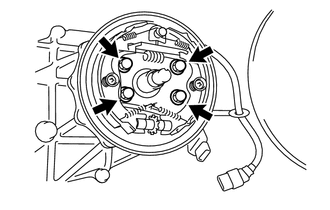
Clean the 4 bolts and bolt installation holes.
Apply adhesive 1344 on the 4 bolts.
Install the parking brake assembly with the 4 bolts.
- Torque:
47 N*m (479 kgf*cm, 35 ft.*lbf)
46501
17.INSTALL PARKING BRAKE DRUM SUB-ASSEMBLY
Install the parking brake drum sub-assembly.
- SST
- 09930-00010
18.ADJUST PARKING BRAKE SHOE
19.INSPECT AND ADJUST PARKING BRAKE LEVER
35073A
20.INSTALL OUTPUT SHAFT NUT
17410
21.INSTALL FRONT EXHAUST PIPE ASSEMBLY
17402
22.INSTALL FRONT NO.2 EXHAUST PIPE SUB-ASSEMBLY
44773D
23.CONNECT SOLENOIDO TO RETARDER HOSE
24.INSTALL CENTER EXHAUST PIPE ASSEMBLY
25.INSTALL EXHAUST PIPE AIR HOSE
89425A
26.INSTALL NO.2 EXHAUST GAS TEMPERATURE SENSOR
89425
27.INSTALL EXHAUST GAS TEMPERATURE SENSOR
17420K
28.INSTALL CENTER NO.2 EXHAUST PIPE ASSEMBLY
17430
29.INSTALL TAIL EXHAUST PIPE ASSEMBLY
30.CONNECT CABLE TO NEGATIVE BATTERY TERMINAL
- Torque:
3.9 N*m (40 kgf*cm, 35 in.*lbf)
31.ADJUST TRANSMISSION FLOOR SHIFT ASSEMBLY
32.INSPECT SHIFT LEVER POSITION
37100
33.INSTALL PROPELLER W/CENTER BEARING SHAFT ASSEMBLY
37110B
34.INSTALL PROPELLER SHAFT GUARD
35.INSTALL NO.1 ENGINE UNDER COVER
36.ADD AUTOMATIC TRANSMISSION FLUID
37.INSPECT AUTOMATIC TRANSMISSION FLUID LEVEL
38.INSPECT FOR OIL LEAK
39.INSPECT FOR EXHAUST GAS LEAK