N04C-VL ENGINE MECHANICAL VALVE CLEARANCE ADJUSTMENT
PROCEDURE

 51441D
1.REMOVE NO. 1 ENGINE UNDER COVER
23670
2.REMOVE INJECTOR ASSEMBLY
3.INSPECT VALVE CLEARANCE
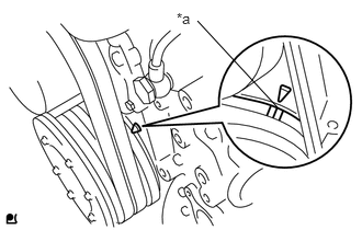
Set the No. 1 cylinder to the TDC/Compression.
| *a | Timing Mark |
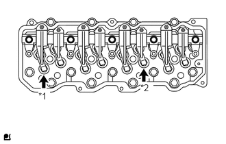
Check the valve clearance of the No. 1 cylinder intake valve and the No. 3 cylinder exhaust valve.
- Valve Clearance (Cold):
- Intake Side:
0.30 mm (0.0118 in.)
- Exhaust Side:
0.45 mm (0.0177 in.)
| *1 | Intake Side No. 1 Cylinder |
| *2 | Exhaust Side No. 3 Cylinder |
- NOTICE:
-
Do not apply excessive force to the valve adjusting screw.
- HINT:
-
If the clearance is not as specified, record the out-of-specification measurement, then adjust the valve clearance.
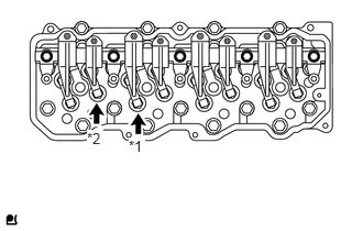
Check the valve clearance of the No. 1 cylinder exhaust valve and the No. 2 cylinder intake valve.
- Valve Clearance (Cold):
- Intake Side:
0.30 mm (0.0118 in.)
- Exhaust Side:
0.45 mm (0.0177 in.)
| *1 | Intake Side No. 2 Cylinder |
| *2 | Exhaust Side No. 1 Cylinder |
- NOTICE:
-
Do not apply excessive force to the valve adjusting screw.
- HINT:
-
If the clearance is not as specified, record the out-of-specification measurement, then adjust the valve clearance.
Turn the crankshaft by a further 360° clockwise.
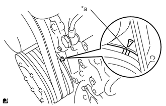
Set the No. 4 cylinder to the TDC/Compression.
| *a | Timing Mark |
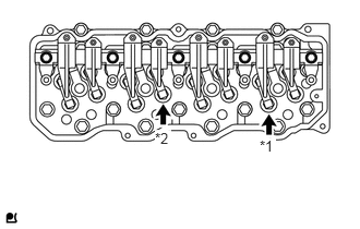
Check the valve clearance of the No. 2 cylinder exhaust valve and the No. 4 cylinder intake valve.
- Valve Clearance (Cold):
- Intake Side:
0.30 mm (0.0118 in.)
- Exhaust Side:
0.45 mm (0.0177 in.)
| *1 | Intake Side No. 4 Cylinder |
| *2 | Exhaust Side No. 2 Cylinder |
- NOTICE:
-
Do not apply excessive force to the valve adjusting screw.
- HINT:
-
If the clearance is not as specified, record the out-of-specification measurement, then adjust the valve clearance.
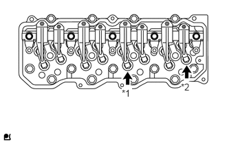
Check the valve clearance of the No. 3 cylinder intake valve and the No. 4 cylinder exhaust valve.
- Valve Clearance (Cold):
- Intake Side:
0.30 mm (0.0118 in.)
- Exhaust Side:
0.45 mm (0.0177 in.)
| *1 | Intake Side No. 3 Cylinder |
| *2 | Exhaust Side No. 4 Cylinder |
- NOTICE:
-
Do not apply excessive force to the valve adjusting screw.
- HINT:
-
If the clearance is not as specified, record the out-of-specification measurement, then adjust the valve clearance.
4.ADJUST VALVE CLEARANCE
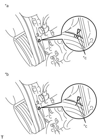
Turn the crankshaft clockwise to align the alignment mark on the crankshaft pulley with the pointer on the timing gear case.
| *a | TDC of No. 1 and No. 4 Cylinder |
| *b | TDC of No. 2 and No. 3 Cylinder |
| *c | Alignment Mark |
- HINT:
-
Turn the crankshaft 1 revolution (360°) to align the matchmark.
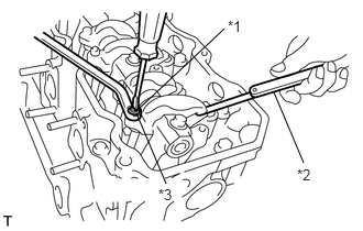
With the No. 1 piston positioned at TDC on the compression stroke, using a feeler gauge, adjust each valve clearance.
- Valve Clearance (Cold):
- Intake Side:
0.30 mm (0.0118 in.)
- Exhaust Side:
0.45 mm (0.0177 in.)
| *1 | Adjusting Screw |
| *2 | Feeler Gauge |
| *3 | Lock Nut |
- HINT:
-
The feeler gauge should move with a very slight pull.
Loosen the lock nut on the valve rocker arm and loosen the adjusting screw.
Insert a 0.30 mm (0.0118 in.) feeler gauge for the intake or a 0.45 mm (0.0177 in.) feeler gauge for the exhaust between the adjusting screw on the valve rocker arm and the valve bridge.
Turn the adjusting screw on the valve rocker arm until the feeler gauge slides with a very slight drag, and lock the adjusting screw with the lock nut.
- Torque:
29 N*m (291 kgf*cm, 21 ft.*lbf)
23670
5.INSTALL INJECTOR ASSEMBLY
51441D
6.INSTALL NO. 1 ENGINE UNDER COVER