AUDIO / VIDEO MICROPHONE AMPLIFIER INSTALLATION
PROCEDURE

 86203
1.INSTALL RADIO WIRE
for LHD:
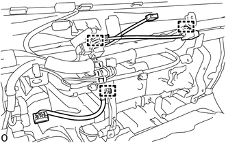
Attach the 3 clamps.
Connect the connector and install the radio wire.
for RHD:
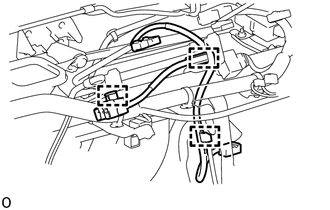
Attach the 3 clamps.
Connect the connector and install the radio wire.
55301
2.INSTALL INSTRUMENT PANEL SUB-ASSEMBLY
86286
3.INSTALL NO. 2 AMPLIFIER BRACKET
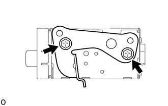
Install the No. 2 amplifier bracket with the 2 screws.
86285
4.INSTALL NO. 1 AMPLIFIER BRACKET
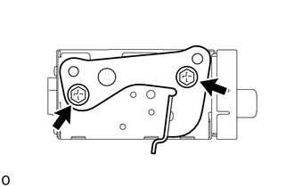
Install the No. 1 amplifier bracket with the 2 screws.
86290A
5.INSTALL MICROPHONE AMPLIFIER ASSEMBLY
Connect the connectors.
Insert the microphone amplifier assembly with bracket.
- NOTICE:
-
When inserting the microphone amplifier, do not press the knobs on it.
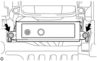
Install the microphone amplifier assembly with the 2 screws.
55412D
6.INSTALL CENTER INSTRUMENT CLUSTER FINISH PANEL
86250
7.INSTALL AMPLIFIER MICROPHONE ASSEMBLY
58841A
8.INSTALL SHIFTING HOLE COVER (for Automatic Transmission)
58123A
9.INSTALL SHIFT AND SELECT LEVER SUPPORT (for Manual Transmission)
Install the shift lever hole cover with the 4 bolts.
58286
10.INSTALL NO. 1 SHIFT AND SELECT LEVER BOOT (for Manual Transmission)
for RHD:
Install the shift lever boot with the 3 bolts.
for LHD:
Install the shift lever boot with the 4 bolts.
58534A
11.INSTALL TRANSMISSION COVER MAT (for Manual Transmission)
Install the transmission cover mat to the shift and select lever support.
33504F
12.INSTALL SHIFT LEVER KNOB SUB-ASSEMBLY (for Manual Transmission)
Gently rotate the shift lever knob sub-assembly by hand until it locks.
After locking, further tighten by 1.5 turns.
After tightening, rotate and adjust the tightened direction so that the shift pattern is positioned within +/-10° of the front of the vehicle.
13.CONNECT CABLE TO NEGATIVE BATTERY TERMINAL
- NOTICE:
-
When disconnecting the cable, some systems need to be initialized after the cable is reconnected.
-
Click hereGeneral>INTRODUCTION>REPAIR INSTRUCTION>INITIALIZATION