1BZ-FPE ENGINE MECHANICAL VALVE CLEARANCE INSPECTION
PROCEDURE

 1.WARM UP AND STOP ENGINE
Allow the engine to warm up to normal operating temperature.
11201
2.REMOVE CYLINDER HEAD COVER
3.SET NO.1 CYLINDER TO TDC/COMPRESSION
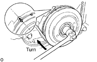
Turn the crankshaft pulley clockwise, and align its groove with the groove of the timing gear cover.
Check that the valve rocker arm on the No.1 cylinder are loose and valve rocker arm on the No.4 cylinder are tight.
If not, turn the crankshaft 1 revolution (360 °) and align the mark as above.
4.INSPECT VALVE CLEARANCE
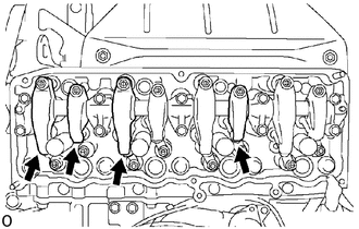
Check only the valves indicated in the illustration.
Using a feeler gauge, measure the clearance between the adjusting screw on the valve rocker arm and the valve bridge.
Record the out-of-specification valve clearance measurements.
- Valve clearance (Hot):
- Intake:
0.20 - 0.25 mm (0.008 - 0.010 in.)
- Exhaust:
0.36 - 0.40 mm (0.014 - 0.016 in.)
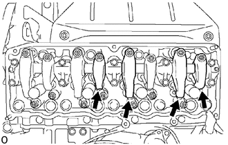
Turn the crankshaft pulley 1 revolution (360 °) and align the mark as above. (See procedure step 3)
Check only the valves indicated as shown. Measure the valve clearance. (See procedure in step (a))
5.ADJUST VALVE CLEARANCE
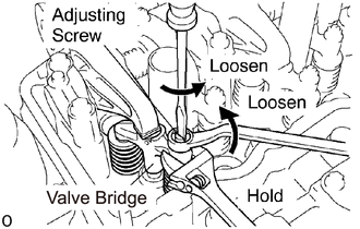
Loosen the lock nut on the valve bridge, and loosen the adjusting screw until the adjusting screw and valve stem are completely separated.
- NOTICE:
-
Hold the valve bridge with a wrench, and loosen the lock nut. Do not apply torque to the valve bridge.
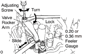
Loosen the lock nut on the valve rocker arm, and loosen the adjusting screw.
Insert a 0.20 mm (0.008 in.) feeler gage for intake or 0.36 mm (0.014 in.) feeler gage for exhaust between the adjusting screw on the valve rocker arm and the valve bridge.
Turn the adjusting screw on the valve rocker arm until the feeler gauge slides with a very slight drag, and lock the adjusting screw with the lock nut.
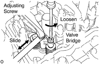
With the feeler gauge, inserted, check that the resistance of the feeler gauge remains the same when the adjusting screw on the valve bridge is loosened.
If the resistance of the feeler gauge changes, repeat from step (b).
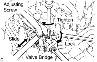
Tighten the adjusting screw on the valve bridge, and lock the adjusting screw with the lock nut when the resistance of the feeler gauge begins to get stronger.
- NOTICE:
-
Hold the valve bridge with a wrench, and lock the adjusting screw with the lock nut. Do not apply torque to the valve bridge.
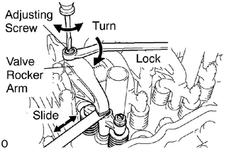
Loosen the lock nut on the valve rocker arm.
Turn the adjusting screw on the valve rocker arm until the feeler gauge slides with a very slight drag, and lock the adjusting screw with the lock nut.
Recheck the valve clearance.
11201
6.REINSTALL CYLINDER HEAD COVER