1BZ-FPE ENGINE MECHANICAL CYLINDER HEAD INSTALLATION
PROCEDURE

 11101
1.INSTALL CYLINDER HEAD
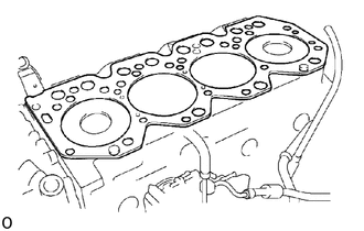
Place cylinder head on cylinder block
Place a new cylinder head gasket in position on the cylinder block.
- NOTICE:
-
Be careful of the installation direction.
Place the cylinder head in position on the cylinder head gasket.
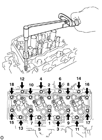
Install cylinder head bolts
- HINT:
- ·
The cylinder head bolts are tightened in 3 progressive steps (steps (b), (d) and (e)).
·If any bolts is broken or deformed, replace it.
Apply a light coat of engine oil on the threads and under the heads of the cylinder head bolts.
Install and uniformly tighten the 18 cylinder head bolts, in several passes, in the sequence shown.
- Torque:
49 N*m (500 kgf*cm, 36 ft*lbf)
If any one of the cylinder head bolts does not meet the torque specification, replace the cylinder head bolt.
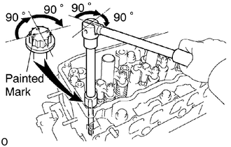
Mark the front of the cylinder head bolt with paint.
Retighten the cylinder head bolts 90 ° in the numerical order shown.
Retighten cylinder head bolts by and additional 90 °.
Check that the painted mark is now facing rearward.
2.INSTALL PUSH RODS
13901
3.INSTALL VALVE ROCKER SHAFT ASSEMBLY
Place the rocker shaft assembly on the cylinder head.
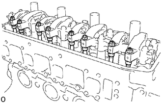
Align the rocker arm adjusting screws with the heads of the push rods.
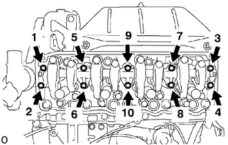
Install and uniformly tighten the 10 bolts, in several passes, in the sequence shown.
- Torque:
25 N*m (255 kgf*cm, 18 ft*lbf)
4.ADJUST VALVE CLEARANCE
11201
5.INSTALL CYLINDER HEAD COVER
Install the gasket to the cylinder head cover.
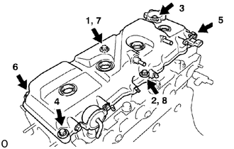
Install and uniformly tighten the cylinder head cover with the 6 cushions, 4 bolts and 2 nuts, in several passes, in the sequence shown.
- Torque:
10.5 N*m (107 kgf*cm, 8 ft*lbf)
17141
6.INSTALL EXHAUST MANIFOLD
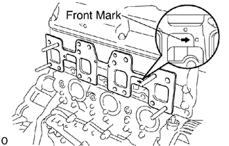
Install a new gasket to the cylinder head as shown.
- NOTICE:
-
Be careful of the installation direction.
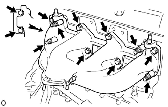
Install the exhaust manifold and No.2 heat insulator with the 6 bolts and new 4 nuts. Uniformly tighten the bolts and nuts in several passes.
- Torque:
47.5 N*m (484 kgf*cm, 35 ft*lbf)
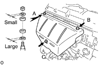
Install the 3 plate washers and 3 spacers to the stud bolts on the exhaust manifold.
- HINT:
-
Install the plate washers with large inside diameter.
Install the heat insulator with the 3 spacers, 3 plate washers and 3 nuts.
- HINT:
-
Install the plate washers with small inside diameter.
Install and tighten the 3 nuts with these order.
First, temporarily tighten nuts A and B. Then fully tighten nuts C, A and B.
- Torque:
18.5 N*m (189 kgf*cm, 14 ft*lbf)
16331
7.INSTALL WATER OUTLET ASSEMBLY
Install a new gasket to the intake manifold.
Connect the water bypass hose to the water pump.
Install the water outlet assembly with the 2 nuts.
- Torque:
18.5 N*m (189 kgf*cm, 14 ft*lbf)
17111
8.INSTALL INTAKE MANIFOLD ASSEMBLY
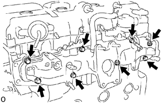
Install a new gasket, intake manifold assembly with the 7 bolts and 2 nuts. Uniformly tighten the bolts and nuts in several passes.
- Torque:
18.5 N*m (189 kgf*cm, 14 ft*lbf)
Connect the water by-pass hose No. 3 and No. 4 to the ISC valve.
16206
9.INSTALL WATER BY-PASS PIPE
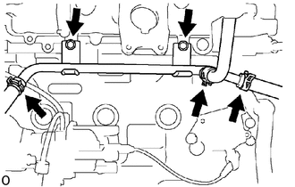
Install the water by-pass pipe with the nut and bolt.
- Torque:
18 N*m (184 kgf*cm, 13 ft*lbf)
Connect the 3 water hoses to the water by-pass pipe.
26200
10.INSTALL CARBURETOR ASSEMBLY
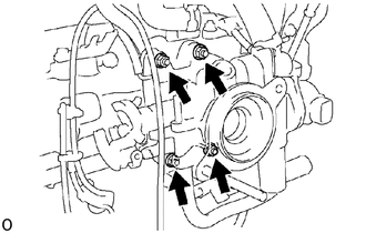
Install a new gasket and the carburetor assembly with the 2 nuts and 2 bolts.
- Torque:
25 N*m (255 kgf*cm, 18 ft*lbf)
Connect the auxiliary air valve hose No. 1 to the ISC valve.
17805
11.INSTALL INTAKE AIR CONNECTOR
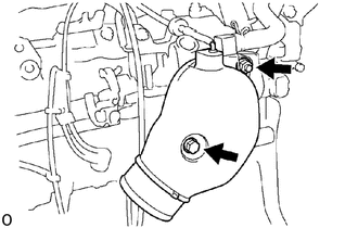
Install a new gasket and the intake air connector with the nut and bolt.
- Torque:
18.5 N*m (189 kgf*cm, 14 ft*lbf)
19100P
12.INSTALL SPARK PLUGS
13.CONNECT HIGH-TENSION CORDS TO SPARK PLUGS
14.CONNECT VACUUM HOSE TO DISTRIBUTOR FILTER
15.CONNECT VACUUM HOSE TO TURBO PRESSURE SENSOR
16.CONNECT PCV HOSES TO CYLINDER HEAD COVER
17.FILL WITH ENGINE COOLANT
18.START ENGINE AND CHECK FOR LEAKS
19.RECHECK ENGINE COOLANT LEVEL AND OIL LEVEL
20.READJUST VALVE CLEARANCE
21. DRIVE BELT