AIR CONDITIONING FRONT COOLING UNIT INSTALLATION
CAUTION / NOTICE / HINT
- HINT:
- ·
Use the same procedure for LHD and RHD vehicles.
·The procedure listed below is for RHD vehicles.
·A bolt without a torque specification is shown in the standard bolt chart.
Click hereGeneral>SPECIFICATIONS>STANDARD BOLT>SPECIFIED TORQUE FOR STANDARD BOLTS
PROCEDURE

 88510
1.INSTALL COOLER UNIT ASSEMBLY
Temporarily install the cooling unit assembly with the 6 bolts.
- NOTICE:
-
Installing the cooler unit assembly from the vehicle must be performed by multiple people.
Tighten the 2 bolts in the order shown in the illustration.
- HINT:
-
The other bolts can be tightened in any order.
Attach the 7 clamps.
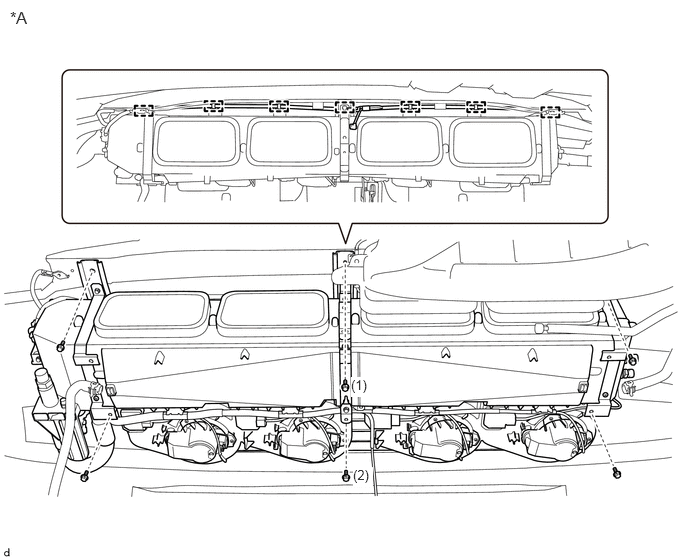
| *A | for RHD | - | - |
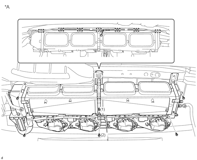
| *A | for LHD | - | - |
Connect the 2 drain cooler hose to the cooler unit assembly.(e) Connect the
Connect the ground wire with the bolt.
Connect the connector.
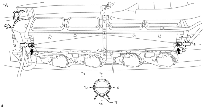
| *A | for RHD | - | - |
| *a | View A | *b | Front of Vehicle |
| *c | Top of Vehicle | *d | Rear of Vehicle |
| *e | Bottom of Vehicle | *f | Marking |
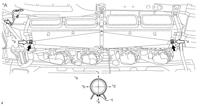
| *A | for LHD | - | - |
| *a | View A | *b | Front of Vehicle |
| *c | Top of Vehicle | *d | Rear of Vehicle |
| *e | Bottom of Vehicle | *f | Marking |
88717B
2.CONNECT COOLER REFRIGERANT SUCTION PIPE B AND COOLER REFRIGERANT LIQUID PIPE D (for RHD)
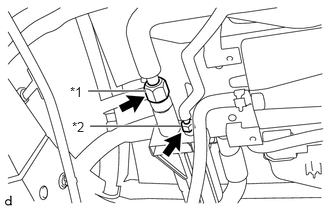
Remove the attached vinyl tape from the pipe.
Apply sufficient compressor oil (ND-OIL 8) to a new O-ring and the fitting surface of the rear cooling unit.
- Compressor oil:
ND-OIL 8 or equivalent
Install the O-ring onto the cooler refrigerant suction pipe B and cooler refrigerant liquid pipe D.
- NOTICE:
-
Keep the O-ring and O-ring fitting surfaces clean from dirt or any foreign objects.
Tighten the cooler refrigerant suction pipe B and cooler refrigerant liquid pipe D onto the cooling unit assembly with the 2 union nuts.
- NOTICE:
-
Do not apply excessive force to the cooler refrigerant suction pipe B and cooler refrigerant liquid pipe D.
- Torque:
- Cooler Refrigerant Suction Pipe B:
42 N*m (428 kgf*cm, 31 ft.*lbf)
- Cooler Refrigerant Liquid Pipe D:
14 N*m (142 kgf*cm, 10 ft.*lbf)
| *1 | Cooler Refrigerant Suction Pipe B |
| *2 | Cooler Refrigerant Liquid Pipe D |
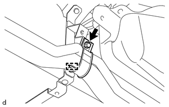
Attach the guide to install the No. 1 cooler clamp.
Install the bolt.
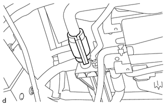
Install new packing to the cooler refrigerant suction pipe B as shown in the illustration.
88717A
3.CONNECT COOLER REFRIGERANT SUCTION PIPE A AND COOLER REFRIGERANT LIQUID PIPE C (for LHD)
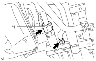
Remove the attached vinyl tape from the pipe.
Apply sufficient compressor oil (ND-OIL 8) to a new O-ring and the fitting surface of the rear cooling unit.
- Compressor oil:
ND-OIL 8 or equivalent
Install the O-ring onto the cooler refrigerant suction pipe A and cooler refrigerant liquid pipe C.
- NOTICE:
-
Keep the O-ring and O-ring fitting surfaces clean from dirt or any foreign objects.
Tighten the cooler refrigerant suction pipe A and cooler refrigerant liquid pipe C onto the cooling unit assembly with the 2 union nuts.
- NOTICE:
-
Do not apply excessive force to the cooler refrigerant suction pipe A and cooler refrigerant liquid pipe C.
- Torque:
- Cooler Refrigerant Suction Pipe A:
42 N*m (428 kgf*cm, 31 ft.*lbf)
- Cooler Refrigerant Liquid Pipe C:
14 N*m (142 kgf*cm, 10 ft.*lbf)
| *1 | Cooler Refrigerant Suction Pipe A |
| *2 | Cooler Refrigerant Liquid Pipe C |
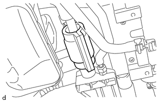
Install new packing to the cooler refrigerant suction pipe A as shown in the illustration.
88430A
4.INSTALL NO. 1 AIR DUCT ASSEMBLY
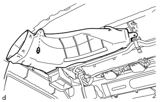
for RHD:
Install the No. 1 air duct assembly with the clip.
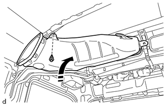
for LHD:
Push up the No. 1 air duct assembly in the direction of the arrow shown in the illustration and install the clip.

|
Push Up Direction |
88430B
5.INSTALL NO. 2 AIR DUCT ASSEMBLY
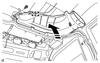
for RHD:
Push up the No. 2 air duct assembly in the direction of the arrow shown in the illustration and install the 2 clips.
Attach the clamp.
|
|
Push Up Direction |
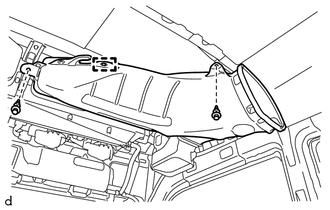
for LHD:
Install the No. 2 air duct assembly with the 2 clips.
Attach the clamp.
63830
6.INSTALL ROOF VENTILATOR DUCT ASSEMBLY
Install the roof ventilator duct assembly with the 3 clips.
Install the 6 bolts.
for Manual Air Conditioning System:
Connect the connector.
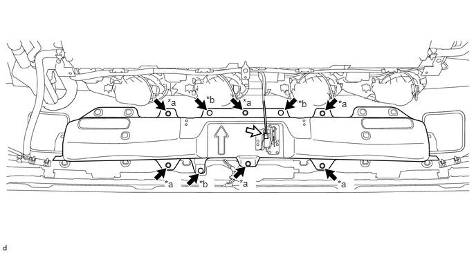
| *a | Bolt | *b | Nut |
Connect the 2 drain cooler hose to the roof ventilator duct assembly.
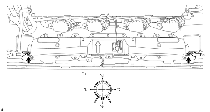
| *a | View A | *b | Front of Vehicle |
| *c | Top of Vehicle | *d | Rear of Vehicle |
| *e | Bottom of Vehicle | *f | Marking |
63925
7.INSTALL NO. 1 COOLER INNER DUCT LH
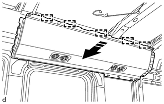
Attach the 5 guides to install the No. 1 cooler inner duct LH as shown in the illustration.
|
|
Install in this Direction |
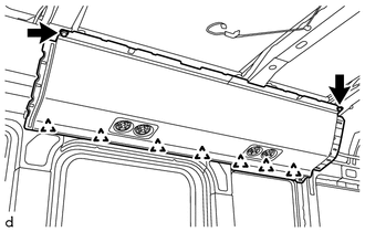
Attach the 7 clips.
Install the 2 screws.
63926
8.INSTALL NO. 2 COOLER INNER DUCT LH
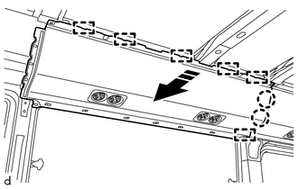
Attach the 2 claws and 6 guides to install the No. 2 cooler inner duct LH as shown in the illustration.
|
|
Install in this Direction |
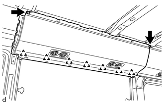
Attach the 7 clips.
Install the 2 screws.
63917A
9.INSTALL NO. 3 COOLER INNER DUCT LH
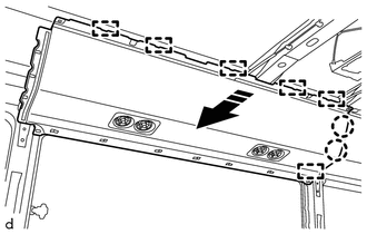
Attach the 2 claws and 6 guides to install the No. 3 cooler inner duct LH as shown in the illustration.
|
|
Install in this Direction |
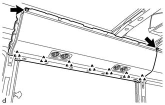
Attach the 7 clips.
Install the 2 screws.
63940
10.INSTALL NO. 4 COOLER INNER DUCT LH (for Long Body)
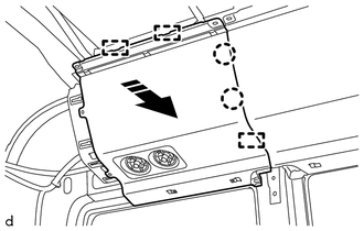
Attach the 2 claws and 3 guides to install the No. 1 cooler inner duct LH as shown in the illustration.
|
|
Install in this Direction |
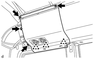
Attach the 3 clips.
Install the 4 screws.
63915
11.INSTALL NO. 1 COOLER INNER DUCT RH
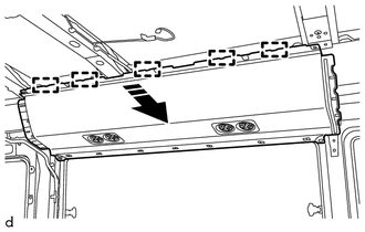
Attach the 6 guides to install the No. 1 cooler inner duct RH as shown in the illustration.
|
|
Install in this Direction |
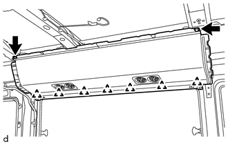
Attach the 7 clips.
Install the 2 screws.
63916
12.INSTALL NO. 2 COOLER INNER DUCT RH
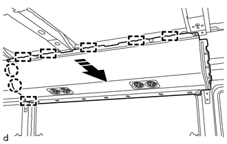
Attach the 2 claws and 6 guides to install the No. 2 cooler inner duct RH as shown in the illustration.
|
|
Install in this Direction |
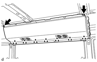
Attach the 7 clips.
Install the 2 screws.
63917
13.INSTALL NO. 3 COOLER INNER DUCT RH
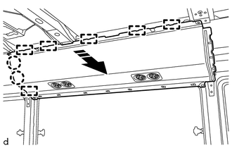
Attach the 2 claws and 6 guides to install the No. 3 cooler inner duct RH as shown in the illustration.
|
|
Install in this Direction |
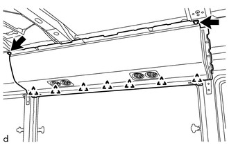
Attach the 7 clips.
Install the 2 screws.
63930
14.INSTALL NO. 4 COOLER INNER DUCT RH (for Long Body)
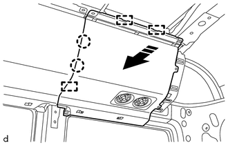
Attach the 2 claws and 3 guides to install the No. 4 cooler inner duct RH as shown in the illustration.
|
|
Install in this Direction |
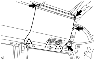
Attach the 3 clips.
Install the 4 screws.
65938
15.INSTALL NO. 3 CURTAIN RAIL (w/ Curtain)
Install the No. 3 curtain rail with the 3 screws.
65936
16.INSTALL NO. 1 CURTAIN RAIL (w/ Curtain)
Install the No. 1 curtain rail with the 7 screws.
- HINT:
-
Use the same procedure for other side.
63310
17.INSTALL ROOF HEADLINING ASSEMBLY
18.CONNECT CABLE TO NEGATIVE BATTERY TERMINAL
19. CHARGE REFRIGERANT
20. WARM UP ENGINE
21.INSPECT FOR REFRIGERANT GAS LEAK