INTERIOR ROOF HEADLINING INSTALLATION
CAUTION / NOTICE / HINT
- HINT:
- ·
Use the same procedure for RHD and LHD vehicles.
·The procedure listed below is for RHD vehicles.
·A bolt without a torque specification is shown in the standard bolt chart.
PROCEDURE

 63316A
1.INSTALL NO. 6 ROOF HEADLINING
w/ Rear Air Duct:
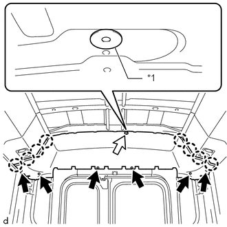
| *1 | Plate |
for Double Swing Out Type:
Install the 7 clips and plate to temporarily install the No. 6 roof headlining.
- HINT:
-
When installing the clips indicated by the white arrow, make sure to install the plate between the No. 6 roof headlining and body.
Attach the 8 claws to install the No. 6 roof headlining.
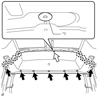
| *1 | Plate |
for Lift Up Type:
Install the 8 clips and plate to temporarily install the No. 6 roof headlining.
- HINT:
-
When installing the clips indicated by the white arrow, make sure to install the plate between the No. 6 roof headlining and body.
Attach the 8 claws to install the No. 6 roof headlining.
w/o Rear Air Duct:
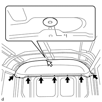
| *1 | Plate |
Install the 8 clips and plate to install the No. 6 roof headlining.
- HINT:
-
When installing the clips indicated by the white arrow, make sure to install the plate between the No. 6 roof headlining and body.
62471D
2.INSTALL REAR UPPER PILLAR GARNISH RH
Attach the 11 clips to install the rear upper pillar garnish RH.
Install the clip.
62472D
3.INSTALL REAR UPPER PILLAR GARNISH LH
- HINT:
-
Use the same procedure described for the RH side.
64735A
4.INSTALL CENTER BACK INNER RAIL GARNISH (for Lift Up Type)
for Tumble Type 4 - Passenger Seat:
Connect the connector.
Attach the 2 guides and 12 clips to install the center back inner rail garnish.
Attach the 10 claws.
for Fixed Type 4 - Passenger Seat:
Connect the connector.
Attach the 8 clips to install the center back inner rail garnish.
Attach the 4 claws.
62487A
5.INSTALL INNER ROOF SIDE GARNISH COVER RH (for Double Swing Out Type)
Attach the 2 clips and 3 claws to install the inner roof side garnish cover RH.
62488A
6.INSTALL INNER ROOF SIDE GARNISH COVER LH (for Double Swing Out Type)
- HINT:
-
Use the same procedure described for the RH side.
63349A
7.INSTALL REAR ROOF HEADLINING GARNISH (for Double Swing Out Type)
Attach the 13 clips to install the rear roof headlining garnish.
65905B
8.INSTALL WINDOW CURTAIN RAIL SUB-ASSEMBLY (w/ Curtain)
Install the 2 window curtain rail sub-assemblies with the 6 screws.
65939
9.INSTALL NO. 4 CURTAIN RAIL (w/ Curtain)
for Standard Body:
Install the No. 4 curtain rail with the 7 screws.
for Long Body:
Install the No. 4 curtain rail with the 3 screws.
65937
10.INSTALL NO. 2 CURTAIN RAIL (w/ Curtain)
- HINT:
-
Use the same procedure described for the No. 4 curtain rail.
63315B
11.INSTALL NO. 5 ROOF HEADLINING BOARD (for Long Body, w/o Rear Air Duct)
Install the No. 5 roof headlining board with the 3 clips.
63324
12.INSTALL NO. 4 ROOF BOARD
w/ Rear Air Duct:
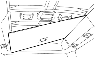
Set the LH side of the No. 4 roof board into the ceiling installation groove as shown in the illustration.
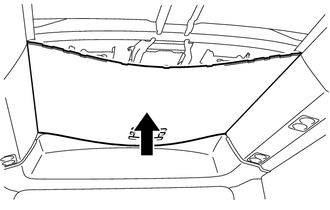
Temporarily install the No. 4 roof board by first bending it to set the RH side into the installation groove and then pressing up on the middle of the No. 4 roof board.
- NOTICE:
-
Do not fold the No. 4 roof board.
for Standard Body, w/ Rear Air Duct:
Install the No. 4 roof board with the 3 clips.
for Long Body, w/ Rear Air Duct:
Install the No. 4 roof board with the 7 clips.
for Standard Body, w/o Rear Air Duct:
Install the No. 4 roof board with the 4 clips.
for Long Body, w/o Rear Air Duct:
Install the No. 4 roof board with the 6 clips.
63372G
13.INSTALL NO. 4 ROOF BOARD SET MOULDING (w/o Rear Air Duct)
Attach the 9 clips to install the No. 4 roof board set moulding.
63372F
14.INSTALL NO. 3 ROOF BOARD SET MOULDING (w/ Rear Air Duct)
w/ Room Rack:
Attach the 6 clips and claw to install the No. 3 roof board set moulding.
w/o Room Rack:
Attach the 7 clips and 2 claws to install the No. 3 roof board set moulding.
63372E
15.INSTALL NO. 2 ROOF BOARD SET MOULDING (for Long Body, w/o Rear Air Duct)
Attach the 9 clips to install the No. 2 roof board set moulding.
86150B
16.INSTALL NO. 2 WITH BOX SPEAKER ASSEMBLY (w/ SPEAKER)
- HINT:
-
Use the same procedure described for the No. 1 with box speaker assembly.
-
Click hereAudio / Visual / Telematics>AUDIO / VIDEO>ROOF SPEAKER>INSTALLATION
63323
17.INSTALL NO. 3 ROOF BOARD
w/ Rear Air Duct:
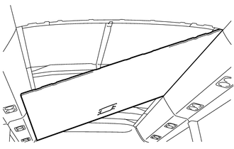
Set the RH side of the No. 3 roof board into the ceiling installation groove as shown in the illustration.
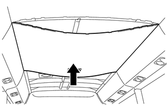
Temporarily install the No. 3 roof board by first bending it to set the LH side into the installation groove and then pressing up on the middle of the No. 3 roof board.
- NOTICE:
-
Do not fold the No. 3 roof board.
Install the No. 3 roof board with the 5 clips.
w/o Rear Air Duct:
Install the No. 3 roof board with the 6 clips.
- NOTICE:
-
Do not fold the No. 3 roof board.
63372D
18.INSTALL NO. 2 ROOF BOARD SET MOULDING
w/ Rear Air Duct:
w/ Room Rack:
Attach the 6 clips to install the No. 2 roof board set moulding.
w/o Room Rack:
Attach the 7 clips to install the No. 2 roof board set moulding.
w/o Rear Air Duct:
Attach the 9 clips to install the No. 2 roof board set moulding.
63322
19.INSTALL NO. 2 ROOF BOARD
w/ Rear Air Duct:
Set the RH side of the No. 2 roof board into the ceiling installation groove as shown in the illustration.
Temporarily install the No. 2 roof board by first bending it to set the LH side into the installation groove and then pressing up on the middle of the No. 2 roof board.
- NOTICE:
-
Do not fold the No. 2 roof board.
Install the No. 2 roof board with the 5 clips.
w/o Rear Air Duct:
Install the No. 2 roof board with the 6 clips.
- NOTICE:
-
Do not fold the No. 2 roof board.
63372A
20.INSTALL NO. 2 ROOF BOARD SET MOULDING
- HINT:
-
Use the same procedure to install the No. 2 roof board set moulding the other side.
81240J
21.INSTALL ROOM LIGHT ASSEMBLY
86150
22.INSTALL NO. 1 WITH BOX SPEAKER ASSEMBLY (w/ SPEAKER)
62452C
23.INSTALL REAR ROOF SIDE RAIL GARNISH LH (w/o Rear Air Duct)
for RHD:
Click hereVehicle Interior>INTERIOR>SIDE PANEL (for RHD)>INSTALLATION
for LHD:
Click hereVehicle Interior>INTERIOR>SIDE PANEL (for LHD)>INSTALLATION
62451E
24.INSTALL REAR ROOF SIDE RAIL GARNISH (w/o Rear Air Duct)
for RHD:.
Click hereVehicle Interior>INTERIOR>SIDE PANEL (for RHD)>INSTALLATION
for LHD:
Click hereVehicle Interior>INTERIOR>SIDE PANEL (for LHD)>INSTALLATION
62431F
25.INSTALL ROOF SIDE RAIL GARNISH (for LHD, Long Body, w/o Rear Air Duct)
62452B
26.INSTALL NO. 3 ROOF SIDE RAIL GARNISH LH (w/o Rear Air Duct)
for RHD:
Click hereVehicle Interior>INTERIOR>SIDE PANEL (for RHD)>INSTALLATION
for LHD:
Click hereVehicle Interior>INTERIOR>SIDE PANEL (for LHD)>INSTALLATION
62451C
27.INSTALL REAR ROOF SIDE RAIL GARNISH RH (w/o Rear Air Duct)
for RHD:
Click hereVehicle Interior>INTERIOR>SIDE PANEL (for RHD)>INSTALLATION
for LHD:
Click hereVehicle Interior>INTERIOR>SIDE PANEL (for LHD)>INSTALLATION
62431F
28.INSTALL ROOF SIDE RAIL GARNISH (for LHD, Long Body, w/o Rear Air Duct)
62451E
29.INSTALL REAR ROOF SIDE RAIL GARNISH (w/o Rear Air Duct)
for RHD:
Click hereVehicle Interior>INTERIOR>SIDE PANEL (for RHD)>INSTALLATION
for LHD:
Click hereVehicle Interior>INTERIOR>SIDE PANEL (for LHD)>INSTALLATION
62451B
30.INSTALL NO. 3 ROOF SIDE RAIL GARNISH RH (w/o Rear Air Duct)
for RHD:
Click hereVehicle Interior>INTERIOR>SIDE PANEL (for RHD)>INSTALLATION
for LHD:
Click hereVehicle Interior>INTERIOR>SIDE PANEL (for LHD)>INSTALLATION
63377C
31.INSTALL NO. 2 ROOF HEADLINING MOULDING (w/o Rear Air Duct)
Attach the guide, 2 clips and claw to install the No. 2 roof headlining moulding.
63378C
32.INSTALL NO. 3 ROOF HEADLINING MOULDING (w/o Rear Air Duct)
- HINT:
-
Use the same procedure to install the No. 2 roof headlining moulding.
62537B
33.INSTALL NO. 3 PILLAR GARNISH RH (w/o Rear Air Duct)
62538B
34.INSTALL NO. 4 PILLAR GARNISH RH (w/o Rear Air Duct)
62539B
35.INSTALL NO. 5 PILLAR GARNISH RH (for Long Body, w/o Rear Air Duct)
62548B
36.INSTALL NO. 4 PILLAR GARNISH LH (w/o Rear Air Duct)
62549B
37.INSTALL NO. 5 PILLAR GARNISH LH (for Long Body, w/o Rear Air Duct)
62638A
38.INSTALL QUARTER PILLAR GARNISH RH (w/o Rear Air Duct)
62639A
39.INSTALL QUARTER PILLAR GARNISH LH (w/o Rear Air Duct)
62989
40.INSTALL CENTER DOOR LOCK COVER (w/o Rear Air Duct)
74730
41.INSTALL HAND GRIP FRAME ASSEMBLY (w/ Hand Grip Frame, w/o Rear Air Duct)
for RHD:
Click hereVehicle Interior>INTERIOR>SIDE PANEL (for RHD)>INSTALLATION
for LHD:
Click hereVehicle Interior>INTERIOR>SIDE PANEL (for LHD)>INSTALLATION
74708
42.INSTALL NO. 2 HAND GRIP FRAME SUB-ASSEMBLY (for RHD, Glide Type, w/o Rear Air Duct)
62425
43.INSTALL CENTER PILLAR GARNISH COVER (w/ Hand Grip Frame, w/o Rear Air Duct)
Attach the 4 claws to install the center pillar garnish cover.
44.INSTALL ROOM RACK ASSEMBLY (w/ Room Rack)
for Standard Body:
Install the room rack assembly with the 10 bolts.
- Torque:
- 29 N*m (296 kgf*cm, 21 ft.*lbf)
- NOTICE:
- ·
Installing the room rack to the vehicle must be performed by multiple people.
·Do not damage the room rack assembly, body exterior or vehicle interior.
for Long Body:
Install the room rack assembly with the 12 bolts.
- Torque:
- 29 N*m (296 kgf*cm, 21 ft.*lbf)
- NOTICE:
- ·
Installing the room rack to the vehicle must be performed by multiple people.
·Do not damage the room rack assembly, body exterior or vehicle interior.
45619K
45.INSTALL KNUCKLE STOPPER COVER (w/ Room Rack)
for Standard Body:
Install the 10 knuckle stopper covers.
for Long Body:
Install the 12 knuckle stopper covers.
63310
46.INSTALL ROOF HEADLINING ASSEMBLY
w/ Rear Air Duct:
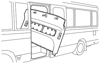
Tilt the roof headlining assembly vertically and carry it onto the vehicle through the center door.
- NOTICE:
- ·
Check that the corners of the roof headlining assembly are not folded, twisted or otherwise deformed and that none of the mounted parts have fallen off.
·Make sure that the roof headlining assembly does not get caught on anything as it may become bent or damaged.
·Do not damage the roof headlining assembly or vehicle interior.
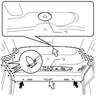
| *1 | Plate |
| *a | Hook |
Attach the hook, 3 clips and 8 claws to install the roof headlining assembly.
Install the 4 clips and 2 plates.
- HINT:
-
When installing the clips indicated by the white arrows, make sure to install the plates between the roof headlining and body.
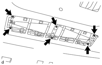
Install the 6 clips.
w/o Rear Air Duct:
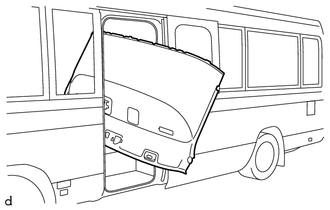
Tilt the roof headlining assembly vertically and carry it onto the vehicle through the center door.
- NOTICE:
- ·
Check that the corners of the roof headlining assembly are not folded, twisted or otherwise deformed and that none of the mounted parts have fallen off.
·Make sure that the roof headlining assembly does not get caught on anything as it may become bent or damaged.
·Do not damage the roof headlining assembly or vehicle interior.
Attach the 3 clips.
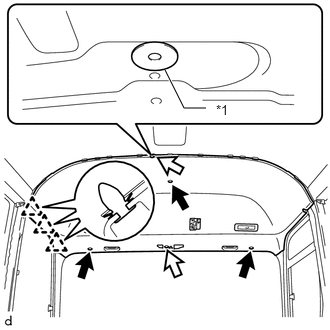
| *1 | Plate |
Install the roof headlining assembly with the 5 clips and 2 plates.
- HINT:
-
When installing the clips indicated by the white arrows, make sure to install the plates between the roof headlining and body.
Install the 2 clips.
63651B
47.INSTALL AIR INTAKE NET (w/ Rear Air Duct)
- HINT:
-
Use the same procedure for both air intake net.
Attach the 9 clips to install the air intake net.
63656D
48.INSTALL CENTER AIR INTAKE COVER (w/ Rear Air Duct)
Attach the guide and 3 clips to install the center air intake cover.
63812
49.INSTALL NO. 2 ROOF VENTILATOR COVER (w/o Rear Air Duct)
Attach the 2 clips and 2 claws to install the No. 2 roof ventilator cover.
55905H
50.INSTALL CONTROL KNOB SUB-ASSEMBLY (w/o Rear Air Duct)
Install the control knob sub-assembly.
87810
51.INSTALL INNER REAR VIEW MIRROR ASSEMBLY
83910G
52.INSTALL CLOCK ASSEMBLY (w/ Clock)
63310A
53.INSTALL ROOF HEADLINING ASSEMBLY HOLE PLUG (w/ Cover)
Attach the 2 clips to install the roof headlining assembly hole plug.
74310
54.INSTALL VISOR ASSEMBLY RH
Attach the clip.
Install the visor assembly RH with the 2 screws.
74320
55.INSTALL VISOR ASSEMBLY LH (w/ Passenger Side Visor)
- HINT:
-
Use the same procedure described for the RH side.
63610
56.INSTALL NO. 1 AIR OUTLET REGISTER ASSEMBLY (w/ Rear Air Duct)
- HINT:
-
Use the same procedure for both No. 1 air outlet register assemblies.
Attach the 6 claws to install the No. 1 air outlet register assembly.
65938
57.INSTALL NO. 3 CURTAIN RAIL (w/ Curtain)
Install the No. 3 curtain rail with the 3 screws.
63371B
58.INSTALL NO. 1 ROOF BOARD SET MOULDING
w/ Rear Air Duct:
Attach the 2 claws and 7 clips to install the No. 1 roof board set moulding.
w/o Rear Air Duct:
Attach the 9 clips to install the No. 1 roof board set moulding.
63375B
59.INSTALL NO. 1 ROOF HEADLINING MOULDING RH (w/o Rear Air Duct)
Attach the 2 clips and claw to install the No. 1 roof headlining moulding RH.
63375D
60.INSTALL ROOF HEADLINING MOULDING (w/o Rear Air Duct)
- HINT:
-
Use the same procedure described for the RH side.
62547B
61.INSTALL NO. 3 PILLAR GARNISH LH
Attach the 4 clips and 4 claws to install the No. 3 pillar garnish LH.
73220
62.CONNECT FRONT SEAT OUTER BELT ASSEMBLY LH (w/ Rear No. 1 Seat)
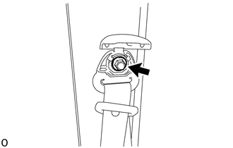
Tighten the bolt to connect the shoulder anchor of the front seat outer belt assembly LH.
- Torque:
- 42 N*m (428 kgf*cm, 31 ft.*lbf)
Check that the front seat outer belt assembly LH is not twisted.
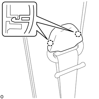
Attach the 2 claws to close the shoulder anchor cover.
74730
63.INSTALL HAND GRIP FRAME ASSEMBLY (w/ Hand Grip Frame)
for Type A:
Install the hand grip frame assembly with the 6 bolts.
for Type B:
Install the hand grip frame assembly with the 6 bolts.
62425
64.INSTALL CENTER PILLAR GARNISH COVER (w/ Hand Grip Frame)
- HINT:
-
Use the same procedure to install the center pillar garnish cover the other side.
62211
65.INSTALL FRONT PILLAR GARNISH RH
Attach the 3 guides and 3 clips to install the front pillar garnish RH.
62212
66.INSTALL FRONT PILLAR GARNISH LH
- HINT:
-
Use the same procedure described for the RH side.
74603
67.INSTALL FRONT ASSIST GRIP SUB-ASSEMBLY
Install the front assist grip sub-assembly with the 2 bolts.
74617V
68.INSTALL ASSIST GRIP PLUG
Attach the 4 claws to install the 2 assist grip plugs.
63951
69.INSTALL COOLER PIPE COVER
Attach the 9 clips and 2 claws to install the cooler pipe cover.
62413A
70.INSTALL LOWER CENTER PILLAR GARNISH RH
Attach the 4 clips and 5 claws to install the lower center pillar garnish RH.
73210
71.CONNECT FRONT SEAT OUTER BELT ASSEMBLY RH
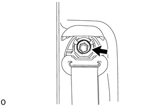
Tighten the bolt to connect the shoulder anchor of the front seat outer belt assembly RH.
- Torque:
- 42 N*m (428 kgf*cm, 31 ft.*lbf)
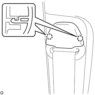
Attach the 2 claws to close the shoulder anchor cover.
Check that the front seat outer belt assembly RH is not twisted.
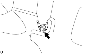
Tighten the bolt to connect the floor anchor of the front seat outer belt assembly RH.
- Torque:
- 42 N*m (428 kgf*cm, 31 ft.*lbf)
73233
72.INSTALL OUTER LAP BELT ANCHOR COVER
62311C
73.INSTALL FRONT DOOR OPENING TRIM WEATHERSTRIP RH
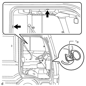
| *a | Paint Mark |

|
Mark Position |
Align the 2 paint marks on the front door opening trim weatherstrip RH with the 2 mark positions on the vehicle and install the front door opening trim weatherstrip RH.
- NOTICE:
- ·
Always align the paint mark when installing the part. If the paint mark position is out of place, water leaks may occur.
·After the installation, check that the corners are properly installed.
- HINT:
-
To easily install the weatherstrip, first install the area with the paint mark as shown in the illustration. Then install the part toward the corners and push any excess length into the corners.
58651A
74.INSTALL FRONT DOOR NO. 1 MAT PLATE
Attach the 4 clamps.
Attach the 3 claws to install the front door No. 1 mat plate with the 2 screws.
46243
75.INSTALL PARKING BRAKE LEVER COVER
Attach the claw to install the parking brake lever cover with the 3 screws.
76.INSTALL REAR NO. 8 SEAT ASSEMBLY (for 4-passenger Seat)
for Tumble Type:
Click hereVehicle Interior>SEAT>REAR SEAT ASSEMBLY (for Tumble Type 4-Passenger Seat)>INSTALLATION
for Fixed Type:
Click hereVehicle Interior>SEAT>REAR SEAT ASSEMBLY (for Fixed Type 4-Passenger Seat)>INSTALLATION
77.INSTALL REAR SEAT ASSEMBLY LH
for Single-Passenger Seat with 3 Point Type Seat Belt:
for Single-Passenger Seat without 3 Point Type Seat Belt:
78.INSTALL REAR SEAT ASSEMBLY RH
for 2-Passenger Seat with Separate Type Seatback:
for 2-Passenger Seat with Bench Type Seatback:
79.INSTALL FRONT PROTECTOR ASSEMBLY RH (for RHD, w/ Protector)
80.INSTALL FRONT SEAT ASSEMBLY
81.CONNECT CABLE TO NEGATIVE BATTERY TERMINAL
- NOTICE:
-
When disconnecting the cable, some systems need to be initialized after the cable is reconnected.
-
Click hereGeneral>INTRODUCTION>REPAIR INSTRUCTION>INITIALIZATION
82.CHECK SRS WARNING LIGHT
for 2 Connector Type:
for 3 Connector Type: