BRAKE CONTROL / DYNAMIC CONTROL SYSTEMS ANTI-LOCK BRAKE SYSTEM(w/o Brake pedal Load Sensing Switch) DTC CHECK / CLEAR
DTC CHECK/CLEAR (When Using GTS)
Check the DTC.
Turn the ignition switch off.
Connect the GTS to the DLC3.
Turn the ignition switch to ON.
Turn the GTS on.
Read the DTCs following the prompts on the GTS screen. Enter the following menus: Chassis / ABS/VSC/TRC / Trouble Codes.
Check the details of the DTCs (Click hereBrake>BRAKE CONTROL / DYNAMIC CONTROL SYSTEMS>ANTI-LOCK BRAKE SYSTEM (w/o Brake pedal Load Sensing Switch)>DIAGNOSTIC TROUBLE CODE CHART).
Clear the DTC.
Turn the ignition switch off.
Connect the GTS to the DLC3.
Turn the ignition switch to ON.
Turn the GTS on.
Operate the GTS to clear the codes. Enter the following menus: Chassis / ABS/VSC/TRC / Trouble Codes.
Clear the DTCs by following the prompts on the GTS.
- HINT:
-
Refer to the GTS operator's manual for further details.
DTC CHECK/CLEAR (When Using SST Check Wire)
Check the DTC.
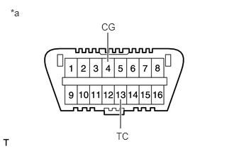
Using SST, connect terminals 13 (TC) and 4 (CG) of the DLC3
- SST
- 09843-18040
| *a | Front view of DLC3 |
Turn the ignition switch to ON.
Observe the blinking pattern of the ABS warning light in order to identify the DTC.
- HINT:
-
If no code appears, inspect the TC and CG terminal circuit, and ABS warning light circuit.
| Trouble Area | See Procedure |
|---|---|
| TC and CG terminal circuit | ( ) |
| ABS warning light circuit (Remains on) | ()
|
| ABS warning light circuit (Does not come on) | ()
|
Count the number of blinks of the ABS warning light.
- HINT:
- ·
When the system is operating correctly, each light will blink continuously in a pattern of 0.25 seconds on, and then 0.25 seconds off.
·When one DTC is output, each light will output the same code at 4 second intervals. (For example, code 21 would be output as 2 blinks, a 1.5 second pause, and then 1 blink.
·When 2 or more DTCs are output, each light will output a different code at 2.5 second intervals, and when all codes have been output, there will be a 4 second pause and the sequence will repeat.
·When multiple codes are stored, they are output in order starting with the lowest DTC number.
Clear the DTC.
Using SST, connect terminals 13 (TC) and 4 (CG) of the DLC3.
- SST
- 09843-18040
| *a | Front view of DLC3 |
Turn the ignition switch to ON.
Clear the DTCs stored in the ECU by depressing the brake pedal 8 times or more within 5 seconds.
Check that the warning light indicates a normal system code.
Remove SST from the terminals of the DLC3.