Home › Brake › BRAKE CONTROL / DYNAMIC CONTROL SYSTEMS › ANTI-LOCK BRAKE SYSTEM (w/o Brake pedal Load Sensing Switch) › 2017.01–2021.01
RM2850E _54 Brake _073264 BRAKE CONTROL / DYNAMIC CONTROL SYSTEMS _0356879 ANTI-LOCK BRAKE SYSTEM(w/o Brake pedal Load Sensing Switch) J

BRAKE CONTROL / DYNAMIC CONTROL SYSTEMS  ANTI-LOCK BRAKE SYSTEM(w/o Brake pedal Load Sensing Switch)  ABS Warning Light Remains ON  


DESCRIPTION

If any of the following is detected, the ABS warning light remains on:

·

The skid control ECU connectors are disconnected from the skid control ECU.

·

There is a malfunction in the skid control ECU internal circuit.

·

There is an open in the harness between the combination meter and the skid control ECU.


HINT:

In some cases, the GTS cannot be used when the skid control ECU is abnormal.


WIRING DIAGRAM
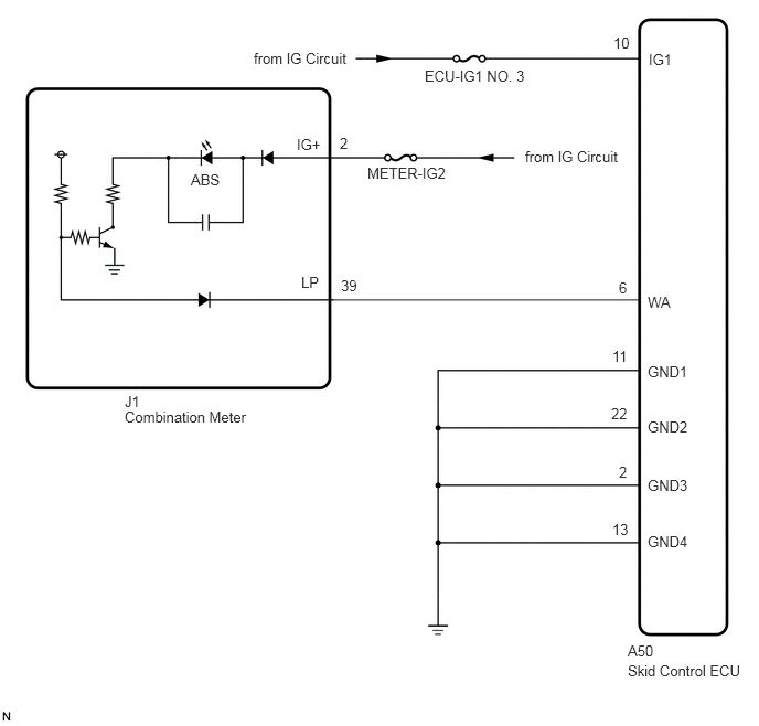
C375244E01
2.396,0.469 3.396,0.719 1,0.25 10 false from IG Circuit 4.01,0.635 5.01,0.885 1,0.25 10 false ECU-IG1 NO. 3 5.792,0.323 6.073,0.552 0.281,0.229 10 false 10 6.125,0.479 6.521,0.76 0.396,0.281 10 false IG1 6.115,2.771 6.448,3 0.333,0.229 10 false WA 6.115,3.427 6.604,3.646 0.49,0.219 10 false GND1 6.115,3.948 6.594,4.167 0.479,0.219 10 false GND2 6.115,4.5 6.688,4.719 0.573,0.219 10 false GND3 6.115,5.031 6.677,5.271 0.563,0.24 10 false GND4 5.927,6.063 6.292,6.292 0.365,0.229 10 false A50 5.781,4.917 6.063,5.146 0.281,0.229 10 false 13 5.844,4.375 6.125,4.604 0.281,0.229 10 false 2 5.771,3.823 6.052,4.052 0.281,0.229 10 false 22 5.781,3.281 6.063,3.51 0.281,0.229 10 false 11 5.844,2.635 6.125,2.865 0.281,0.229 10 false 6 4.958,1.396 5.917,1.635 0.958,0.24 10 false from IG Circuit 3.469,1.552 4.333,1.802 0.865,0.25 10 false METER-IG2 3.208,1.271 3.49,1.5 0.281,0.229 10 false 2 2.802,1.281 3.083,1.51 0.281,0.229 10 false IG+ 3.219,2.615 3.5,2.844 0.281,0.229 10 false 39 2.844,2.583 3.125,2.813 0.281,0.229 10 false LP 1.802,1.615 2.208,1.865 0.406,0.25 10 false ABS 1.177,3.708 1.458,3.938 0.281,0.229 10 false J1 1.177,3.854 2.604,4.125 1.427,0.271 10 false Combination Meter 5.927,6.25 7.104,6.479 1.177,0.229 10 false Skid Control ECU

CAUTION / NOTICE / HINT

NOTICE:

Inspect the fuses for circuits related to this system before performing the following inspection procedure.


PROCEDURE

1.CHECK IF SKID CONTROL ECU CONNECTOR IS SECURELY CONNECTED
a.

Check if the skid control ECU connector is securely connected.

OK:

The connector should be securely connected.


Result:
Proceed to
OK
NG


OK

2.CHECK BATTERY

NG

CONNECT CONNECTOR TO ECU CORRECTLY

2.CHECK BATTERY
a.

Check the battery voltage.

Standard Voltage:

11 to 14 V


Result:
Proceed to
OK
NG


OK

3.INSPECT SKID CONTROL ECU (IG1 TERMINAL)

NG

CHECK OR REPLACE CHARGING SYSTEM OR BATTERY

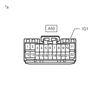
3.INSPECT SKID CONTROL ECU (IG1 TERMINAL)
a.
C215683E05
1.573,0.865 1.958,1.094 0.385,0.229 2.313,1.583 2.563,0.99 2.563,0.99 2.74,0.99 true 0.167,0.156 0.479,0.354 0.313,0.198 10 false *a 1.646,0.896 1.958,1.094 0.313,0.198 10 false A50 2.823,0.906 3.135,1.104 0.313,0.198 10 false IG1

Disconnect the skid control ECU connector.


b.

Turn the ignition switch to ON.


c.

Measure the voltage according to the value(s) in the table below.

Standard Voltage:
Tester Connection Switch Condition Specified Condition
A50-10 (IG1) -Body ground Ignition switch ON 11 to 14 V

Text in Illustration
*a Front view of wire harness connector
(to Skid Control ECU)


Result:
Proceed to
OK
NG


OK

4.INSPECT SKID CONTROL ECU (GND TERMINAL)

NG

REPAIR OR REPLACE HARNESS OR CONNECTOR (IG1 CIRCUIT)

4.INSPECT SKID CONTROL ECU (GND TERMINAL)
a.

Turn the ignition switch off.


b.

Measure the resistance according to the value(s) in the table below.

Standard Resistance:
Tester Connection Condition Specified Condition
A50-11 (GND1) - Body ground Always Below 1 Ω
A50-22 (GND2) - Body ground Always Below 1 Ω
A50-2 (GND3) - Body ground Always Below 1 Ω
A50-13 (GND4) - Body ground Always Below 1 Ω


Result:
Proceed to
OK
NG


OK

5.CHECK HARNESS AND CONNECTOR (SKID CONTROL ECU - COMBINATION METER)

NG

REPAIR OR REPLACE HARNESS OR CONNECTOR (GND CIRCUIT)

5.CHECK HARNESS AND CONNECTOR (SKID CONTROL ECU - COMBINATION METER)
a.

Disconnect the combination meter connector.


b.

Measure the resistance according to the value(s) in the table below.

Standard Resistance:
Tester Connection Condition Specified Condition
A50-6 (WA) - J1-39 (LP) Always Below 1 Ω
A50-6 (WA) - Body ground Always 10 kΩ or higher


Result:
Proceed to
OK
NG


OK

6.INSPECT COMBINATION METER ASSEMBLY

NG

REPAIR OR REPLACE HARNESS OR CONNECTOR

6.INSPECT COMBINATION METER ASSEMBLY
a.

Reconnect the skid control ECU connector.


b.

Reconnect the combination meter connector.


c.

Check the combination meter (Click hereVehicle Interior>METER / GAUGE / DISPLAY>METER / GAUGE SYSTEM>HOW TO PROCEED WITH TROUBLESHOOTING).

OK:

The combination meter is normal.


HINT:

If troubleshooting has been carried out according to the Problem Symptoms Table, refer back to the table and proceed to the next step (Click hereBrake>BRAKE CONTROL / DYNAMIC CONTROL SYSTEMS>ANTI-LOCK BRAKE SYSTEM (w/o Brake pedal Load Sensing Switch)>PROBLEM SYMPTOMS TABLE).


Result:
Proceed to
OK
NG


OK

REPLACE SKID CONTROL ECU

NG

REPLACE COMBINATION METER ASSEMBLY