AUDIO / VIDEO AUDIO AND VISUAL SYSTEM Speaker Circuit
DESCRIPTION
The radio receiver assembly sends sound signals to the speaker (w/o microphone amplifier).
The microphone amplifier assembly receives sound signals from the radio receiver assembly, and sends sound signals to the speakers (w/ microphone amplifier).
WIRING DIAGRAM
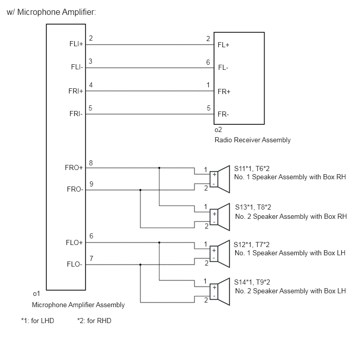
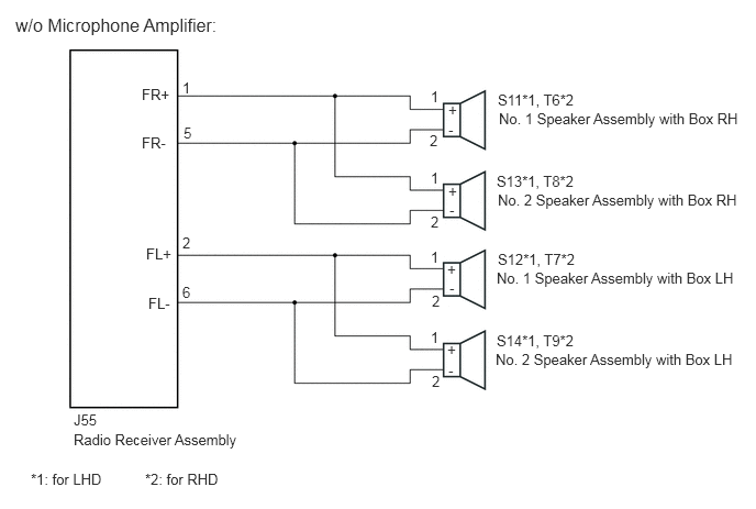
PROCEDURE
Check the vehicle condition.
- Result:
Vehicle Condition Proceed to w/ microphone amplifier A w/o microphone amplifier B
A
B
Disconnect the o2 connectors from the radio receiver assembly.
Disconnect the o1 connector from the microphone amplifier assembly.
Measure the resistance according to the value(s) in the table below.
- Standard Resistance:
Tester Connection Condition Specified Condition o2-2 (FL+) - o1-2 (FLI+) Always Below 1 Ω o2-6 (FL-) - o1-3 (FLI-) Always Below 1 Ω o2-1 (FR+) - o1-4 (FRI+) Always Below 1 Ω o2-5 (FR-) - o1-5 (FRI-) Always Below 1 Ω o2-2 (FL+) - Body ground Always 10 kΩ or higher o2-6 (FL-) - Body ground Always 10 kΩ or higher o2-1 (FR+) - Body ground Always 10 kΩ or higher o2-5 (FR-) - Body ground Always 10 kΩ or higher
- Result:
Proceed to OK NG
OK
NG
*1: for LHD
*2: for RHD
Disconnect the S11, S12, S13 and S14 connectors from the speaker*1.
Disconnect the T6, T7, T8 and T9 connectors from the speaker*2.
Disconnect the o1 connector from the microphone amplifier assembly.
Measure the resistance according to the value(s) in the table below.
- Standard Resistance:
for Front Side (for LHD) Tester Connection Condition Condition Specified Condition S11-1 (+) - o1-8 (FRO+) Always Below 1 Ω S11-2 (-) - o1-9 (FRO-) Always Below 1 Ω S12-1 (+) - o1-6 (FLO+) Always Below 1 Ω S12-2 (-) - o1-7 (FLO-) Always Below 1 Ω S11-1 (+) - Body ground Always 10 kΩ or higher S11-2 (-) - Body ground Always 10 kΩ or higher S12-1 (+) - Body ground Always 10 kΩ or higher S12-2 (-) - Body ground Always 10 kΩ or higher
for Front Side (for RHD) Tester Connection Condition Condition Specified Condition T6-1 (+) - o1-8 (FRO+) Always Below 1 Ω T6-2 (-) - o1-9 (FRO-) Always Below 1 Ω T7-1 (+) - o1-6 (FLO+) Always Below 1 Ω T7-2 (-) - o1-7 (FLO-) Always Below 1 Ω T6-1 (+) - Body ground Always 10 kΩ or higher T6-2 (-) - Body ground Always 10 kΩ or higher T7-1 (+) - Body ground Always 10 kΩ or higher T7-2 (-) - Body ground Always 10 kΩ or higher
for Rear Side (for LHD) Tester Connection Condition Condition Specified Condition S13-1 (+) - o1-8 (FRO+) Always Below 1 Ω S13-2 (-) - o1-9 (FRO-) Always Below 1 Ω S14-1 (+) - o1-6 (FLO+) Always Below 1 Ω S14-2 (-) - o1-7 (FLO-) Always Below 1 Ω S13-1 (+) - Body ground Always 10 kΩ or higher S13-2 (-) - Body ground Always 10 kΩ or higher S14-1 (+) - Body ground Always 10 kΩ or higher S14-2 (-) - Body ground Always 10 kΩ or higher
for Rear Side (for RHD) Tester Connection Condition Condition Specified Condition T8-1 (+) - o1-8 (FRO+) Always Below 1 Ω T8-2 (-) - o1-9 (FRO-) Always Below 1 Ω T9-1 (+) - o1-6 (FLO+) Always Below 1 Ω T9-2 (-) - o1-7 (FLO-) Always Below 1 Ω T8-1 (+) - Body ground Always 10 kΩ or higher T8-2 (-) - Body ground Always 10 kΩ or higher T9-1 (+) - Body ground Always 10 kΩ or higher T9-2 (-) - Body ground Always 10 kΩ or higher
- Result:
Proceed to OK NG
OK
NG
Remove the No. 1 speaker assembly with box.
Click hereAudio / Visual / Telematics>AUDIO / VIDEO>ROOF SPEAKER>REMOVAL
Inspect the No. 1 speaker assembly with box.
Click hereAudio / Visual / Telematics>AUDIO / VIDEO>ROOF SPEAKER>INSPECTION
- Result:
Proceed to OK NG
OK
NG
Remove the No. 2 speaker assembly with box.
Click hereAudio / Visual / Telematics>AUDIO / VIDEO>ROOF SPEAKER>REMOVAL
Inspect the No. 2 speaker assembly with box.
Click hereAudio / Visual / Telematics>AUDIO / VIDEO>ROOF SPEAKER>INSPECTION
- Result:
Proceed to OK NG
OK
NG
Temporarily replace the microphone amplifier assembly with a new or normally functioning one.
Recheck that audio sound can be heard from the speaker.
- OK:
Audio sound can be heard.
- Result:
Proceed to OK NG
OK
NG
*1: for LHD
*2: for RHD
Disconnect the S11, S12, S13 and S14 connectors from the speaker*1.
Disconnect the T6, T7, T8 and T9 connectors from the speaker*2.
Disconnect the J55 connector from the radio receiver assembly.
Measure the resistance between the speaker and the radio receiver assembly according to the value(s) in the table below.
- Standard Resistance:
for Front Side (for LHD) Tester Connection Condition Condition Specified Condition S11-1 (+) - J55-1 (FR+) Always Below 1 Ω S11-2 (-) - J55-5 (FR-) Always Below 1 Ω S12-1 (+) - J55-2 (FL+) Always Below 1 Ω S12-2 (-) - J55-6 (FL-) Always Below 1 Ω S11-1 (+) - Body ground Always 10 kΩ or higher S11-2 (-) - Body ground Always 10 kΩ or higher S12-1 (+) - Body ground Always 10 kΩ or higher S12-2 (-) - Body ground Always 10 kΩ or higher
for Front Side (for RHD) Tester Connection Condition Condition Specified Condition T6-1 (+) - J55-1 (FR+) Always Below 1 Ω T6-2 (-) - J55-5 (FR-) Always Below 1 Ω T7-1 (+) - J55-2 (FL+) Always Below 1 Ω T7-2 (-) - J55-6 (FL-) Always Below 1 Ω T6-1 (+) - Body ground Always 10 kΩ or higher T6-2 (-) - Body ground Always 10 kΩ or higher T7-1 (+) - Body ground Always 10 kΩ or higher T7-2 (-) - Body ground Always 10 kΩ or higher
for Rear Side (for LHD) Tester Connection Condition Condition Specified Condition S13-1 (+) - J55-1 (FR+) Always Below 1 Ω S13-2 (-) - J55-5 (FR-) Always Below 1 Ω S14-1 (+) - J55-2 (FL+) Always Below 1 Ω S14-2 (-) - J55-6 (FL-) Always Below 1 Ω S13-1 (+) - Body ground Always 10 kΩ or higher S13-2 (-) - Body ground Always 10 kΩ or higher S14-1 (+) - Body ground Always 10 kΩ or higher S14-2 (-) - Body ground Always 10 kΩ or higher
for Rear Side (for RHD) Tester Connection Condition Condition Specified Condition T8-1 (+) - J55-1 (FR+) Always Below 1 Ω T8-2 (-) - J55-5 (FR-) Always Below 1 Ω T9-1 (+) - J55-2 (FL+) Always Below 1 Ω T9-2 (-) - J55-6 (FL-) Always Below 1 Ω T8-1 (+) - Body ground Always 10 kΩ or higher T8-2 (-) - Body ground Always 10 kΩ or higher T9-1 (+) - Body ground Always 10 kΩ or higher T9-2 (-) - Body ground Always 10 kΩ or higher
- Result:
Proceed to OK NG
OK
NG
Remove the No. 1 speaker assembly with box.
Click hereAudio / Visual / Telematics>AUDIO / VIDEO>ROOF SPEAKER>REMOVAL
Inspect the No. 1 speaker assembly with box.
Click hereAudio / Visual / Telematics>AUDIO / VIDEO>ROOF SPEAKER>INSPECTION
- Result:
Proceed to OK NG
OK
NG
Remove the No. 2 speaker assembly with box.
Click hereAudio / Visual / Telematics>AUDIO / VIDEO>ROOF SPEAKER>REMOVAL
Inspect the No. 2 speaker assembly with box.
Click hereAudio / Visual / Telematics>AUDIO / VIDEO>ROOF SPEAKER>INSPECTION
- Result:
Proceed to OK NG
OK
NG