2TR-FE ENGINE MECHANICAL ENGINE UNIT REASSEMBLY
PROCEDURE

 1.INSTALL STUD BOLT
Using an E7 "TORX" socket wrench, install the stud bolts B and D.
- Torque:
- Stud bolt B and D:
7.5 N*m (76 kgf*cm, 66 in.*lbf)
Using an E8 "TORX" socket wrench, install the stud bolt A.
- Torque:
- Stud bolt A:
7.5 N*m (76 kgf*cm, 66 in.*lbf)
Apply adhesive to the holes for the stud bolts C on the cylinder block. Using an E7 "TORX" socket wrench, install the stud bolts C.
- Torque:
- Stud bolt C:
7.5 N*m (76 kgf*cm, 66 in.*lbf)
- NOTICE:
-
If the stud bolt is deformed or the threads are damaged, replace it.
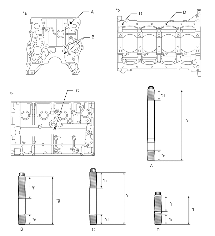
| *a | Front Side | *b | Lower Side |
| *c | Exhaust Side | *d | 12 mm (0.47 in.) |
| *e | 85 mm (3.35 in.) | *f | 25 mm (0.98 in.) |
| *g | 55 mm (2.17 in.) | *h | 18 mm (0.71 in.) |
| *i | 60 mm (2.36 in.) | *j | 20 mm (0.79 in.) |
| *k | 13 mm (0.51 in.) | *l | 35 mm (1.38 in.) |
11114A
2.INSTALL STRAIGHT PIN
Using a plastic-faced hammer, tap new straight pins into the cylinder block.
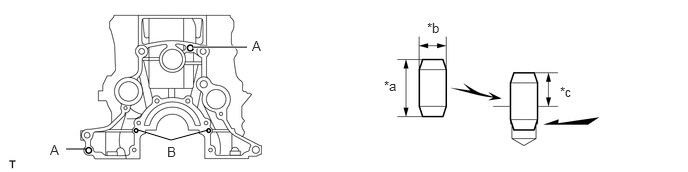
| *a | A: 22 mm (0.87 in. )
B: 14 mm (0.55 in. ) |
*b | A: 10 mm (0.39 in. )
B: 6 mm (0.24 in. ) |
| *c | A: 13 mm (0.51 in. )
B: 5.5 mm (0.217 in. ) |
- | - |
3.INSTALL RING PIN
Using a plastic-faced hammer, tap new ring pins into the cylinder block.
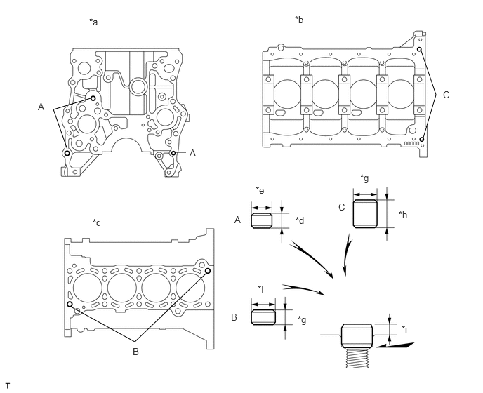
| *a | Front Side | *b | Lower Side |
| *c | Upper Side | *d | 9 mm (0.354 in. ) |
| *e | 11 mm (0.433 in. ) | *f | 15 mm (0.591 in. ) |
| *g | 14 mm (0.551 in. ) | *h | 20 mm (0.787 in. ) |
| *i | A: 3.5 to 4.5 mm (0.138 to 0.177 in. )
B: 7.5 to 9.5 mm (0.295 to 0.374 in. ) C: 7.0 to 9.0 mm (0.276 to 0.354 in. ) |
- | - |
13633
4.INSTALL NO. 2 BALANCESHAFT DRIVEN GEAR
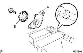
Mount the No. 2 balanceshaft head in a vise.
- NOTICE:
-
Be careful not to damage the No. 2 balanceshaft.
Install the No. 2 balanceshaft thrust plate (A) and No. 2 balanceshaft driven gear (B).
Install the bolt.
- Torque:
36 N*m (365 kgf*cm, 26 ft.*lbf)
13622
5.INSTALL NO. 2 BALANCESHAFT
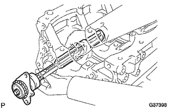
Install the No. 2 balanceshaft into the cylinder block.
- NOTICE:
-
When installing the No. 2 balanceshaft, support the No. 2 balanceshaft with both hands and avoid scratching the balanceshaft bearing on the cylinder block.
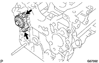
Install the 2 bolts.
- Torque:
18 N*m (184 kgf*cm, 13 ft.*lbf)
13632
6.INSTALL NO. 1 BALANCESHAFT DRIVEN GEAR
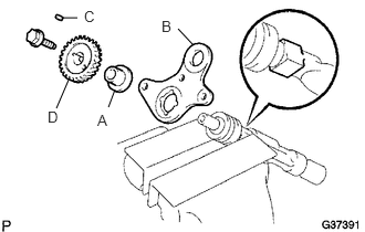
Mount the No. 1 balanceshaft head in a vise.
- NOTICE:
-
Be careful not to damage the No. 1 balanceshaft.
Install the balanceshaft thrust spacer (A), No. 1 balanceshaft thrust plate (B), sliding key (C) and No. 1 balanceshaft driven gear (D).
Install the bolt.
- Torque:
36 N*m (365 kgf*cm, 26 ft.*lbf)
13621
7.INSTALL NO. 1 BALANCESHAFT
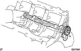
Install the No. 1 balanceshaft into the cylinder block.
- NOTICE:
-
When installing the No. 1 balanceshaft, support the No. 1 balanceshaft with both hands and avoid scratching the balanceshaft bearing on the cylinder block.
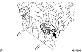
Install and tighten the bolt.
- Torque:
18 N*m (184 kgf*cm, 13 ft.*lbf)
8.CHECK BALANCESHAFT THRUST CLEARANCE
15708
9.INSTALL NO. 1 OIL NOZZLE SUB-ASSEMBLY
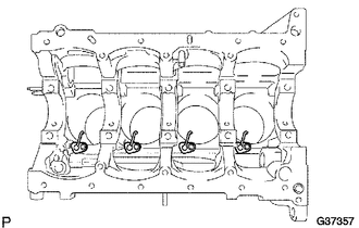
Using an E7 "TORX" socket wrench, install the 4 No. 1 oil nozzle sub-assemblies.
- Torque:
7.0 N*m (71 kgf*cm, 62 in.*lbf)
11415
10.INSTALL CYLINDER BLOCK WATER DRAIN COCK SUB-ASSEMBLY
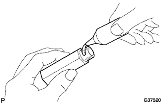
Apply adhesive around the cylinder block water drain cock sub-assembly.
- Seal packing:
Toyota Genuine Adhesive 1324, Three Bond 1324 or equivalent
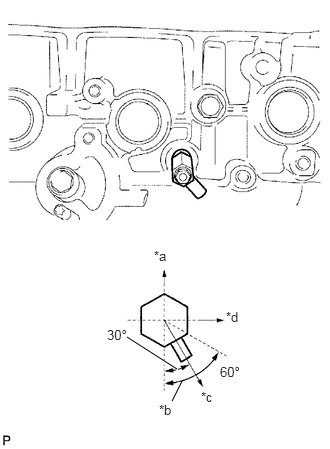
Install the cylinder block water drain cock sub-assembly as shown in the illustration.
- Torque:
25 N*m (250 kgf*cm, 18 ft.*lbf)
Install the water drain cock plug onto the cylinder block water drain cock sub-assembly.
- Torque:
13 N*m (130 kgf*cm, 9 ft.*lbf)
| *a | Upper Side |
| *b | Allowable Range |
| *c | Target Direction |
| *d | Front |
- NOTICE:
- ·
Do not rotate the cylinder block water drain cock sub-assembly more than 1 revolution (360°) after tightening the cylinder block water drain cock sub-assembly to the specified torque.
·Do not loosen the cylinder block water drain cock sub-assembly to adjust it. If an adjustment is necessary, remove the cylinder block water drain cock sub-assembly and reinstall it.
·Install the cylinder block water drain cock sub-assembly within 3 minutes after applying adhesive.
13101
11.INSTALL PISTON SUB-ASSEMBLY WITH PIN
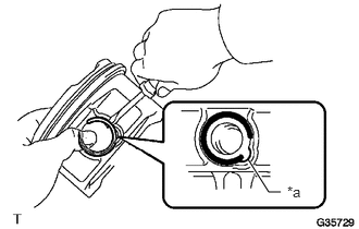
Assemble the piston and connecting rod.
Using a small screwdriver, install a new snap ring at one end of the piston pin hole.
| *a | Service hole |
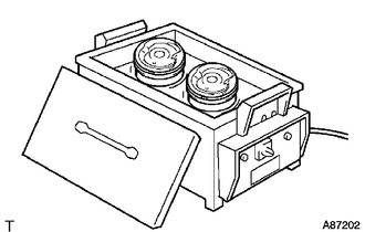
Gradually heat the piston to between 80 to 90°C (176 to 194°F).
Coat the piston pin with engine oil.
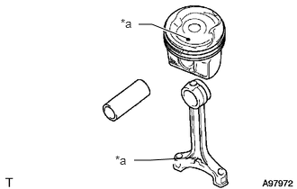
Align the front marks on the piston and connecting rod, and push in the piston pin with your thumb.
| *a | Front Mark |
- HINT:
-
The piston and pin are a matched set.
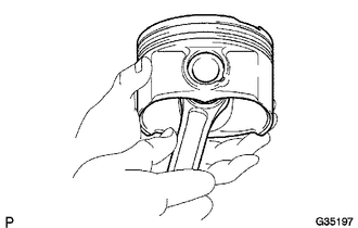
Check the fit between the piston and piston pin by trying to move the piston back and forth on the piston pin.
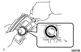
Using a small screwdriver, install a new snap ring at the other end of the piston pin hole.
| *a | Service hole |
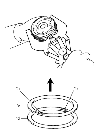
Install the piston rings.
Install the oil ring expander and 2 side rails by hand.
Using a piston ring expander, install the 2 compression rings with the code mark as shown in the illustration.
| *a | Code Mark (1N) |
| *b | Code Mark (2N) |
| *c | No. 1 |
| *d | No. 2 |

|
Upward |
- HINT:
- ·
Install the No. 1 compression ring with the code mark (1N) facing upward.
·Install the No. 2 compression ring with the code mark (2N) facing upward.
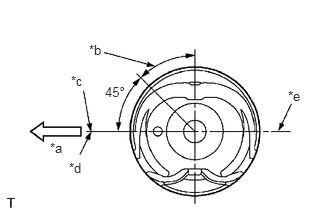
Position the piston rings so that the ring ends are as shown in the illustration.
| *a | Front |
| *b | Expander |
| *c | Oil Ring Rail |
| *d | No. 1 Compression |
| *e | No. 2 Compression |
- NOTICE:
-
Do not align the ring ends.
13041
12.INSTALL CONNECTING ROD BEARING
Align the bearing claw with the groove of the connecting rod or connecting cap.
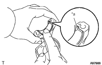
Install the bearings onto the connecting rod and connecting rod cap.
| *a | Claw |
- NOTICE:
-
Clean the back side of the bearing and the bearing surface of the connecting rod. The surface should be free of dust and oil.
11711
13.INSTALL CRANKSHAFT BEARING
- NOTICE:
-
Do not apply engine oil to the bearing contact area and back side.
Clean the main journal, and the interior and exterior of the bearing.
Install the upper bearing.
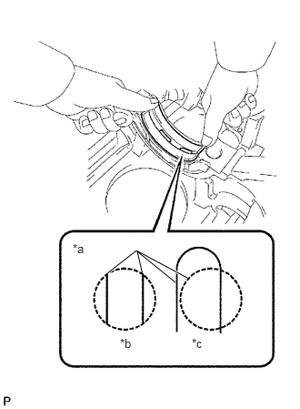
Install the upper bearing onto the cylinder block so that the upper bearing lubrication hole is centered within the cylinder block lubrication hole, as shown in the illustration.
- Reference (Difference in dimension of cylinder block and upper bearing):
Item Specified Condition # 1, 5 journal 3.75 mm (0.1476 in.) # 3 journal 1.75 mm (0.0689 in.) # 2, 4 journal 2.75 mm (0.1083 in.)
| *a | Bearing Hole |
| *b | CORRECT |
| *c | INCORRECT |
- NOTICE:
-
Do not apply engine oil to the bearing contact area and backside.
Install the lower bearing.
Install the lower bearing onto the bearing cap.
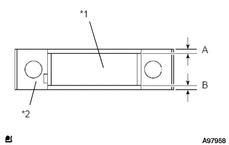
Using a vernier caliper, measure the distance between the bearing cap edge and the lower bearing edge.
- Standard dimension (A - B):
0.3 mm (0.0118 in.) or less
- Reference: (Dimension of A or B):
Item Specified Condition # 1, 5 journal 3.83 mm (0.1508 in.) # 3 journal 1.74 mm (0.0685 in.) # 2, 4 journal 2.75 mm (0.1083 in.)
| *a | Lower Bearing |
| *b | Bearing Cap |
- NOTICE:
-
Do not apply engine oil to the bearing contact area and backside.
With the upper bearing and lower bearing installed, use a plastic-faced hammer to install the bearing caps to the cylinder block.
- NOTICE:
-
Make sure that the bearing cap front mark and journal number are correct.
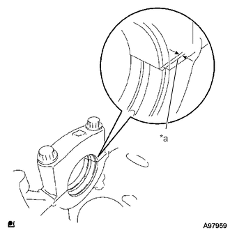
Using a vernier caliper, measure the amount of misalignment between the upper bearing and lower bearing, as shown in the illustration.
- Standard value:
0.9 mm (0.035 in.) or less
| *a | Misalignment |
Remove the bearing cap.
13411
14.INSTALL CRANKSHAFT
- NOTICE:
-
The crankshaft bearing cap bolt is tightened in 2 progressive steps.
Install the upper crankshaft thrust washer onto the cylinder block.
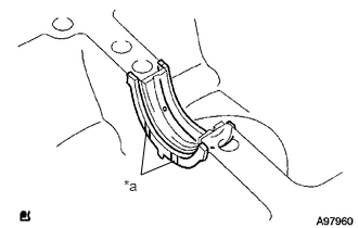
Install the 2 thrust washers onto the No. 3 journal position of the cylinder block with the oil grooves facing outward.
| *a | Oil Groove |
- NOTICE:
-
Be careful when installing the upper and lower thrust bearings as they are similar but cannot be interchanged.
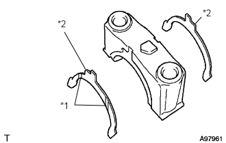
Install the 2 thrust washers onto the No. 3 bearing cap with the oil grooves facing outward.
| *a | Oil Groove |
| *b | Claw |
- NOTICE:
-
Be careful when installing the upper and lower thrust bearings as they are similar but cannot be interchanged. The lower bearing has a claw as shown in the illustration.
Apply engine oil to the upper bearing, then place the crankshaft on the cylinder block.
Apply engine oil to the lower bearing.
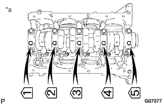
Install the 5 crankshaft bearing caps in their proper locations.
| *a | Engine Front |
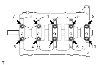
Install the crankshaft bearing cap bolts.
- HINT:
- ·
The main bearing cap bolts are tightened in 2 progressive steps.
·If any of the main bearing cap bolts are broken or deformed, replace them as necessary.
Install and uniformly tighten the 10 main bearing cap bolts in the sequence shown in the illustration.
- Torque:
39 N*m (398 kgf*cm, 29 ft.*lbf)
If any main bearing cap bolt does not meet the torque specification, replace it.
Mark the front of the bearing cap bolts with paint.
Tighten the bearing cap bolts by a further 90° in the sequence above.
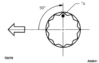
Check that the painted mark is now at a 90° angle to the front.
| *a | Paint Mark |

|
Engine Front |
Check that the crankshaft turns smoothly.
15.CHECK CRANKSHAFT THRUST CLEARANCE
16.INSTALL PISTON WITH CONNECTING ROD
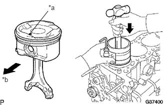
Using a piston ring compressor, push the correctly numbered piston and connecting rod assembly into the appropriate cylinders with the front mark on the piston facing forward.
| *a | Front Mark |
| *b | Front |
Match the numbered connecting rod cap with the connecting rod.
Align the pins of the connecting rod cap with the pin holes on the connecting rod, and install the connecting rod cap.
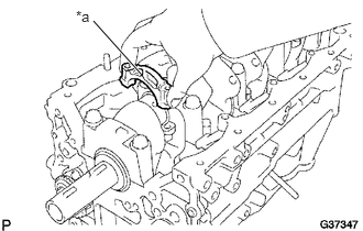
Check that the front mark on the connecting rod cap is facing forward.
| *a | Front Mark |
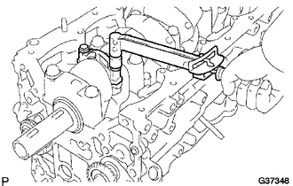
Install the connecting rod cap bolts.
- HINT:
- ·
The connecting rod cap bolts are tightened in 2 progressive steps.
·If any connecting rod bolt is broken or deformed, replace it.
Apply a light coat of engine oil to the threads and under the heads of the connecting rod cap bolts.
Install and alternately tighten the connecting rod cap bolts in several passes.
- Torque:
25 N*m (250 kgf*cm, 18 ft.*lbf)
If any connecting rod cap bolt does not meet the torque specification, replace it.
Mark the front of the connecting rod cap bolts with paint.
Retighten the connecting rod cap bolts 90° as shown in the illustration.
Check that the painted mark is now at a 90° angle to the front.
| *a | Paint Mark |
|
|
Engine Front |
Check that the crankshaft turns smoothly.
17.CHECK CONNECTING ROD THRUST CLEARANCE
18.INSTALL RING PIN
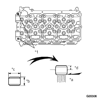
Using a plastic-faced hammer, tap in a new ring pin until the pin stops.
| *a | Ring Pin |
| *b | Until Pin Stop |
| *c | 7 mm (0.28 in. ) |
| *d | 10 mm (0.39 in. ) |
| *e | 2.5 to 3.8 mm (0.10 to 0.15 in. ) |
19.INSTALL NO. 1 STRAIGHT SCREW PLUG
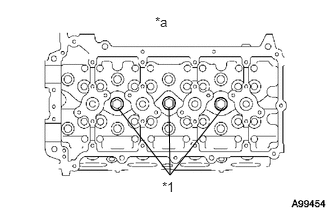
Using a 10 mm hexagon wrench, install 3 new gaskets and 3 No. 1 straight screw plugs.
- Torque:
44 N*m (449 kgf*cm, 32 ft.*lbf)
| *1 | No. 1 Straight Screw Plug |
| *a | for Upper Side |
20.INSTALL NO. 2 STRAIGHT SCREW PLUG
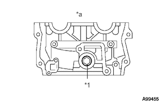
Using a 19 mm hexagon wrench, install a new gasket and the No. 2 straight screw plug.
- Torque:
140 N*m (1428 kgf*cm, 103 ft.*lbf)
| *1 | No. 2 Straight Screw Plug |
| *a | for Front Side |
21.INSTALL STUD BOLT
Using E5 and E7 "TORX" socket wrenches, install the stud bolts.
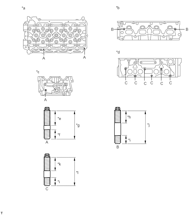
- Torque:
- A:
3.0 N*m (31 kgf*cm, 27 in.*lbf)
- B:
7.5 N*m (76 kgf*cm, 66 in.*lbf)
- C:
7.5 N*m (76 kgf*cm, 66 in.*lbf)
| *a | Upper Side | *b | Intake Side |
| *c | Front Side | *d | Exhaust Side |
| *e | 21 mm (0.83 in. ) | *f | 9 mm (0.35 in. ) |
| *g | 34 mm (1.34 in. ) | *h | 24 mm (0.94 in. ) |
| *i | 13 mm (0.51 in. ) | *j | 45 mm (1.77 in. ) |
| *k | 20 mm (0.79 in. ) | *l | 35 mm (1.38 in. ) |
15678A
22.INSTALL OIL CONTROL VALVE FILTER
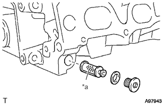
Check that no foreign matter is on the mesh part of the oil control valve filter.
| *a | Mesh Part |
If foreign objects are present, clean the filter thoroughly.
Using an 8 mm hexagon wrench, install a new gasket and the oil control valve filter with the screw plug.
- Torque:
30 N*m (306 kgf*cm, 22 ft.*lbf)
13734
23.INSTALL VALVE SPRING SEAT
13711A
24.INSTALL VALVE STEM OIL O-SEAL OR RING
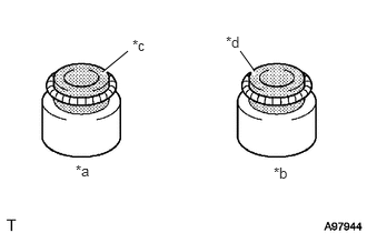
Apply a light coat of engine oil to a new valve stem oil O-seal or ring.
| *a | Intake Side |
| *b | Exhaust Side |
| *c | White |
| *d | Black |
- NOTICE:
-
Pay close attention when installing the intake and exhaust oil seals. For example, installing the intake oil seal into the exhaust or installing the exhaust oil seal into the intake can cause installation problems later.
- HINT:
-
The intake valve oil seal is white and the exhaust valve oil seal is black.
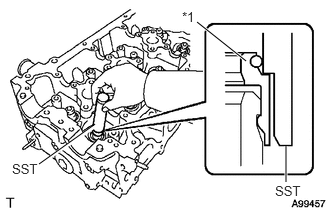
Using SST, push in the valve stem oil O-seal or ring.
- SST
- 09201-41020
| *1 | Valve Stem Oil O-seal or Ring |
- NOTICE:
-
Failure to use SST will cause the seal to be damaged or improperly seated.
13711
25.INSTALL INTAKE VALVE
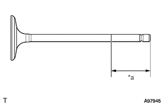
Apply plenty of engine oil to the tip area of the intake valve indicated in the illustration.
| *a | 30 mm(1.18 in.) or more |
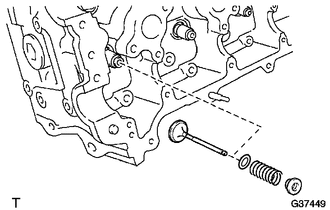
Install the intake valve, valve spring seat, compression spring and retainer into the cylinder head sub-assembly.
- NOTICE:
-
Install the same parts in the same combination at their original locations.
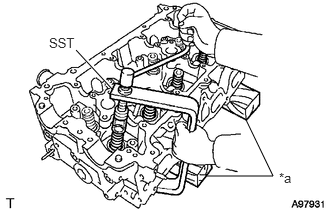
Using SST and wooden blocks, compress the compression spring and install the 2 valve spring retainer locks.
- SST
- 09202-70020
| *a | Wooden Block |
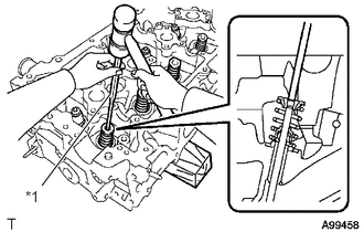
Using a 5 mm pin punch and plastic-faced hammer, lightly tap the valve stem tip to ensure a proper fit.
| *a | Pin Punch(5 mm) |
- NOTICE:
-
Be careful not to damage the valve stem tip.
13715
26.INSTALL EXHAUST VALVE
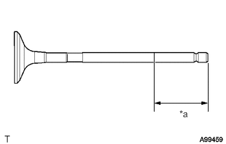
Apply plenty of engine oil to the tip area of the exhaust valve indicated in the illustration.
| *a | 30 mm(1.18 in.) or more |
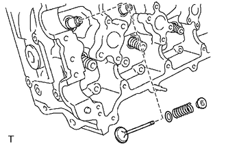
Install the exhaust valve, valve spring seat, compression spring and retainer into the cylinder head sub-assembly.
- NOTICE:
-
Install the same parts in the same combination at their original locations.
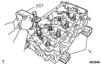
Using SST and wooden blocks, compress the compression spring and install the 2 valve spring retainer locks.
- SST
- 09202-70020
| *a | Wooden Block |
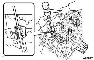
Using a 5 mm pin punch and plastic-faced hammer, lightly tap the valve stem tip to ensure a proper fit.
| *a | Pin Punch(5 mm) |
- NOTICE:
-
Be careful not to damage the valve stem tip.
13750
27.INSTALL VALVE LASH ADJUSTER ASSEMBLY
- NOTICE:
- ·
Keep the valve lash adjuster assembly free from dirt and foreign objects.
·Only use clean engine oil.
Place the valve lash adjuster assembly into a container full of engine oil.
Insert the tip of SST into the lash adjuster plunger and use the tip to press down on the check ball inside the plunger.
- SST
- 09276-75010
Squeeze the SST and lash adjuster together to move the plunger up and down 5 or 6 times.
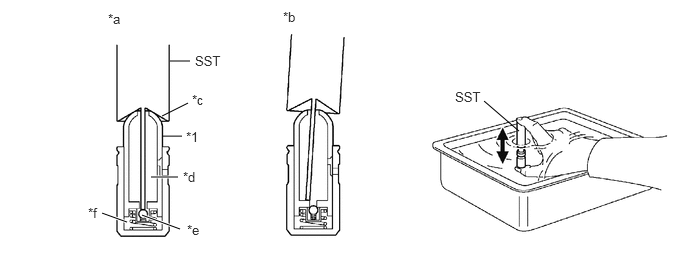
| *1 | Plunger | - | - |
| *a | CORRECT | *b | INCORRECT |
| *c | Tapered Part | *d | Low Pressure Chamber |
| *e | Check Ball | *f | High Pressure Chamber |
Check the movement of the plunger and bleed air.
- OK:
Plunger moves up and down.
- NOTICE:
-
When bleeding high-pressure air from the compression chamber, make sure that the tip of the SST is actually pressing the check ball as shown in the illustration. If the check ball is not pressed, air will not bleed.
After bleeding air, remove SST. Then, try to quickly and firmly press the plunger with a finger.
- OK:
Plunger is very difficult to move.
If the result is not as specified, replace the valve lash adjuster assembly.
- NOTICE:
-
Install the valve lash adjuster assemblies at their original locations.
13716
28.INSTALL VALVE STEM CAP
Apply a light coat of engine oil to the valve stem cap.
Install the valve stem cap onto the cylinder head sub-assembly.
13801
29.INSTALL NO. 1 VALVE ROCKER ARM SUB-ASSEMBLY
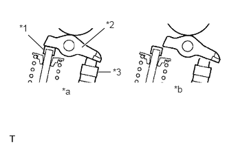
Apply clean engine oil to the valve lash adjuster tip and valve stem cap surface. Then install the No. 1 valve rocker arm sub-assembly.
| *1 | Valve Stem Cap |
| *2 | No. 1 Valve Rocker Arm Sub-assembly |
| *3 | Valve Lash Adjuster Sub-assembly |
| *a | CORRECT |
| *b | INCORRECT |
- NOTICE:
-
Install the valve stem cap, valve lash adjuster sub-assembly and No. 1 valve rocker arm sub-assembly at their original locations.
13471A
30.INSTALL CRANKSHAFT PULLEY SET CRANKSHAFT KEY
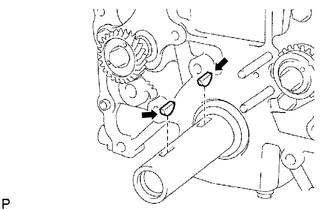
Install the 2 crankshaft pulley set crankshaft keys into the crankshaft.
13554
31.INSTALL NO. 4 CHAIN VIBRATION DAMPER
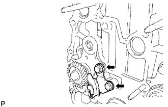
Install the No. 4 chain vibration damper with the 2 bolts.
- Torque:
18 N*m (184 kgf*cm, 13 ft.*lbf)
13507
32.INSTALL NO. 2 CHAIN SUB-ASSEMBLY
- NOTICE:
-
Check that the No. 1 cylinder is at TDC and that the weights of the No. 1 and No. 2 balance shafts are at the bottom.
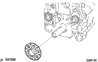
Install the No. 2 crankshaft timing sprocket as shown in the illustration.
- HINT:
-
Install the No. 2 crankshaft timing sprocket with the front mark facing outward.
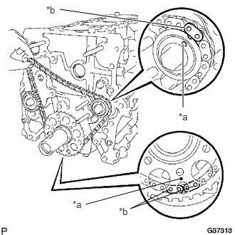
As shown in the illustration, install the No. 2 chain sub-assembly onto the No. 2 crankshaft timing sprocket and baranceshaft drive gear sub-assembly with the mark plates aligned with the timing marks on the No. 2 crankshaft timing sprocket and baranceshaft drive gear sub-assembly.
| *a | Timing Mark |
| *b | Mark Plate |
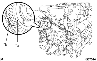
Fit the other mark plate of the balance shaft drive gear sub-assembly behind the large timing mark on the balance shaft drive gear sub-assembly.
| *a | Large Timing Mark |
| *b | Mark Plate |
Insert the balance shaft drive gear shaft into the balance shaft drive gear sub-assembly so that it fits into the thrust plate hole.
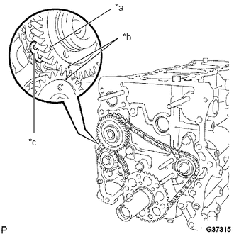
Align the small timing mark on the balance shaft drive gear sub-assembly with the timing mark on the balance shaft timing gear sub-assembly.
| *a | Large Timing Mark |
| *b | Small Timing Mark |
| *c | Mark Plate |
Install the bolt into the balance shaft drive gear sub-assembly and tighten it.
- Torque:
25 N*m (255 kgf*cm, 18 ft.*lbf)
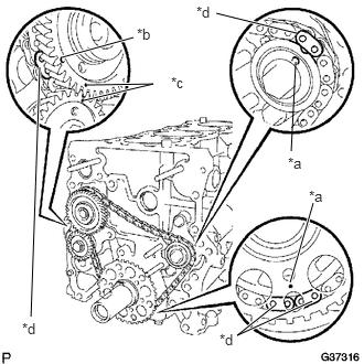
Check that each timing mark is aligned with with the corresponding mark plate.
| *a | Timing Mark |
| *b | Large Timing Mark |
| *c | Small Timing Mark |
| *d | Mark Plate |
- NOTICE:
-
Check that the No. 1 cylinder is at TDC and that the weights of the No. 1 and No. 2 balance shafts are at the bottom.
13550
33.INSTALL NO. 2 CHAIN TENSIONER ASSEMBLY
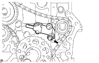
Install the No. 2 chain tensioner assembly with the nut.
- Torque:
18 N*m (184 kgf*cm, 13 ft.*lbf)
- NOTICE:
-
Assemble the No. 2 chain tensioner assembly with the pin installed, then remove the pin after assembly. When doing this, avoid pushing the vibration damper against the chain sub-assembly.
Move the stopper plate downward to release the lock, and push the plunger deep into the tensioner.
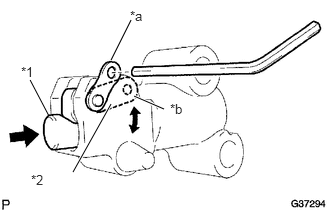
Move the stopper plate upward to set the lock, and insert a hexagon wrench into the hole on the stopper plate.
| *1 | Plunger |
| *2 | Stopper Plate |
| *a | Upward |
| *b | Downward |
13563
34.INSTALL NO. 3 CHAIN VIBRATION DAMPER
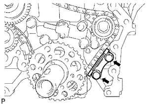
Install the No. 3 chain vibration damper with the 2 bolts.
- Torque:
18 N*m (184 kgf*cm, 13 ft.*lbf)
13562
35.INSTALL NO. 2 CHAIN VIBRATION DAMPER
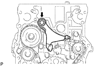
Install the No. 2 chain vibration damper with the bolt.
- Torque:
27 N*m (270 kgf*cm, 20 ft.*lbf)
11381
36.INSTALL ENGINE REAR OIL SEAL RETAINER
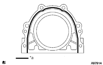
Apply seal packing in a continuous line as shown in the illustration.
- Seal packing:
Toyota Genuine Seal Packing Black, Three Bond 1207B or equivalent
- Standard seal diameter:
2 to 3 mm (0.079 to 0.118 in.)
| *a | Seal packing |
- NOTICE:
- ·
Remove any oil from the contact surface.
·Install the engine rear oil seal retainer within 3 minutes of applying the seal packing.
·Do not start the engine for at least 2 hours after installing.
Install the engine rear oil seal retainer with the 6 bolts.
- Torque:
13 N*m (133 kgf*cm, 10 ft.*lbf)
15609
37.INSTALL OIL FILTER BRACKET SUB-ASSEMBLY
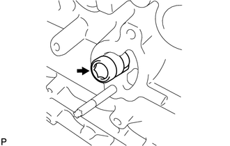
Using a 14 mm hexagon wrench, install the oil filter bracket union.
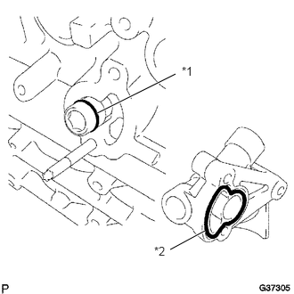
Install a new gasket onto the oil filter bracket sub-assembly.
| *1 | O-ring |
| *2 | Gasket |
- NOTICE:
-
Apply a light coat of engine oil to the new gasket.
Install a new O-ring and gasket onto the oil filter bracket union.
- NOTICE:
-
Apply a light coat of engine oil to the new O-ring.
Install the oil filter bracket sub-assembly with the 2 bolts and nut.
- Torque:
25 N*m (255 kgf*cm, 18 ft.*lbf)
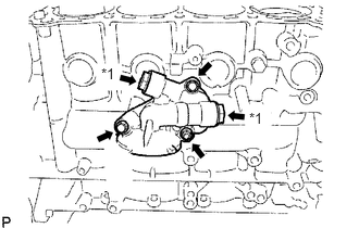
Install 2 new gaskets and 2 screw plugs onto the oil filter bracket sub-assembly.
- Torque:
49 N*m (500 kgf*cm, 36 ft.*lbf)
| *1 | Screw plug |
15710
38.INSTALL OIL COOLER ASSEMBLY
Install the oil cooler assembly with oil cooler union.
- Torque:
43 N*m (439 kgf*cm, 32 ft.*lbf)
15601
39.INSTALL OIL FILTER SUB-ASSEMBLY
Check and clean the oil filter installation surface.
Apply clean engine oil to a new oil filter gasket.
Lightly screw the oil filter sub-assembly into place, and tighten it until the gasket contacts the seat.
Using SST, tighten the oil filter sub-assembly.
When using a torque wrench:
Using a torque wrench to tighten the oil filter sub-assembly.
- Torque:
17 N*m (175 kgf*cm, 13 ft.*lbf)
When not using a torque wrench:
Tighten the oil filter sub-assembly 3/4 of a turn using a common wrench.
11115
40.INSTALL CYLINDER HEAD GASKET
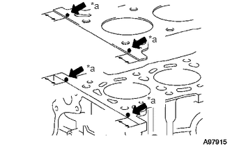
Apply seal packing to the cylinder block upper side and cylinder head gasket upper side as shown in the illustration.
- Standard seal diameter:
4 to 7 mm (0.15 to 0.28 in.)
- Seal packing:
Toyota Genuine Seal Packing 1282B, Three Bond 1282B or equivalent
| *1 | 15 mm (0.591 in. ) |
- NOTICE:
- ·
Remove any oil from the contact surface.
·Install the cylinder head gasket within 3 minutes of applying the seal packing.
·Install the cylinder head sub-assembly within 15 minutes of applying the seal packing.
·Do not put in engine oil within 4 hours of installation.
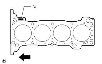
Place a new cylinder head gasket on the cylinder block surface with the Lot No. stamp facing upward.
| *a | Lot No. |
|
|
Front |
- NOTICE:
- ·
Make sure the installation direction is correct.
·Place the cylinder head gently to avoid damaging the cylinder head gasket with the bottom part of the cylinder head sub-assembly.
11101
41.INSTALL CYLINDER HEAD SUB-ASSEMBLY
- HINT:
-
The cylinder head set bolts are tightened in 3 progressive steps.
Place the cylinder head sub-assembly on the cylinder block.
Apply a light coat of engine oil to the threads and under the heads of the cylinder head set bolts.
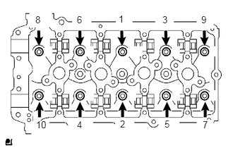
Using a 10 mm bi-hexagon wrench, install and uniformly tighten the 10 cylinder head set bolts with the 10 plate washers, in several passes, in the sequence shown.
- Torque:
39 N*m (398 kgf*cm, 29 ft.*lbf)
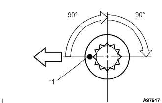
Mark the front of the cylinder head set bolt head with paint.
Tighten the cylinder head set bolts by a further 90° in the sequence shown.
Further tighten the cylinder head set bolts by an additional 90°.
Check that the painted mark is now facing rearward.
| *1 | Paint mark |
|
|
Engine Front |
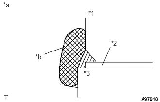
Seal packing will seep out of the front side of the engine. Thoroughly wipe away any seal packing.
| *1 | Cylinder Head Sub-assembly |
| *2 | Cylinder Head Gasket |
| *3 | Cylinder Block |
| *a | Engine Front Side |
| *b | Wipe Away |
13050
42.INSTALL CAMSHAFT TIMING GEAR ASSEMBLY
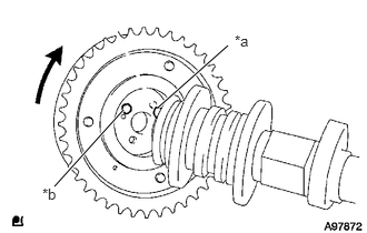
Put the camshaft timing gear assembly and No. 1 camshaft together with the straight pin and key groove misaligned.
Check that there is no gap between the gear flange and the No. 1 camshaft.
- Torque:
78 N*m (795 kgf*cm, 58 ft.*lbf)
With the camshaft timing gear assembly fixed in place, tighten the bolt.
| *a | Straight Pin |
| *b | Key Groove |
13523
43.INSTALL CAMSHAFT TIMING GEAR OR SPROCKET
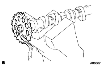
Clamp the No. 2 camshaft in a vise and then install the camshaft timing gear or sprocket onto the No. 2 camshaft with the bolt.
- Torque:
78 N*m (795 kgf*cm, 58 ft.*lbf)
- NOTICE:
-
Be careful not to damage the No. 2 camshaft in the vise.
13511
44.INSTALL CAMSHAFT
Apply clean engine oil to the cam portion of the camshaft and the cylinder head journals.
Set the No. 1 camshaft and No. 2 camshaft as shown in the illustration.
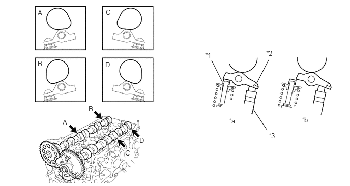
| *1 | Valve Stem Cap | *2 | No. 1 Valve Rocker Arm Sub-assembly |
| *3 | Valve Lash Adjuster Sub-assembly | - | - |
| *a | CORRECT | *b | INCORRECT |
- NOTICE:
-
Before and after setting the No. 1 camshaft and No. 2 camshaft, firmly set the No. 1 valve rocker arm sub-assembly onto the valve lash adjuster sub-assembly.
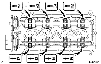
Temporarily install the No. 1 camshaft bearing cap.
Check the proper location of each of the 8 No. 2 camshaft bearing caps and install them.
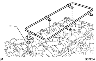
Install a new O-ring onto the No. 1 camshaft bearing cap.
| *1 | O-ring |
Temporarily install the oil delivery pipe.
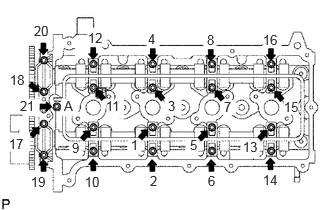
Tighten the 21 bolts and 20 washers in the order shown in the illustration.
- Torque:
- Bolt A:
12 N*m (122 kgf*cm, 9 ft.*lbf)
- except Bolt A:
16 N*m (158 kgf*cm, 11 ft.*lbf)
13521
45.INSTALL CRANKSHAFT TIMING GEAR OR SPROCKET
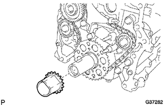
Install the crankshaft timing gear or sprocket as shown in the illustration.
13561
46.INSTALL NO. 1 CHAIN VIBRATION DAMPER
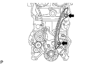
Install the vibration damper with the bolt and nut.
- Torque:
- for bolt:
21 N*m (214 kgf*cm, 15 ft.*lbf)
- for nut:
18 N*m (184 kgf*cm, 13 ft.*lbf)
Remove the hexagon wrench from the No. 2 chain tensioner and release the plunger.
13506
47.INSTALL CHAIN SUB-ASSEMBLY
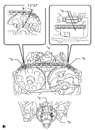
As shown in the illustration, install the chain sub-assembly onto the sprocket and gear with the painted marks aligned with the timing marks on the sprocket and gear.
| *1 | Plunger |
| *a | Timing Mark |
| *b | Mark Plate |
| *c | Stopper Plate |
- HINT:
- ·
The camshaft mark plate is pink.
·The crankshaft mark plate is yellow.
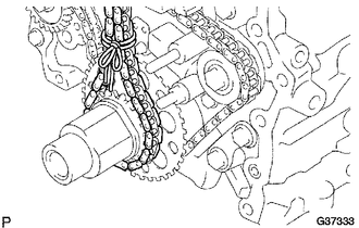
Use a rope to tie the chain sub-assembly of the No. 2 crankshaft timing sprocket. Tie the rope near the sprocket.
- NOTICE:
-
After the chain tensioner has been installed, the rope must be removed.
- HINT:
-
The rope is tied so that the chain sub-assembly will not jump a tooth.
13559
48.INSTALL CHAIN TENSIONER SLIPPER
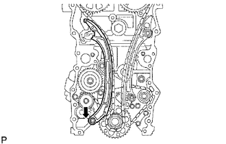
Install the chain tensioner slipper with the bolt.
- Torque:
21 N*m (214 kgf*cm, 15 ft.*lbf)
13540
49.INSTALL NO. 1 TIMING CHAIN TENSIONER ASSEMBLY
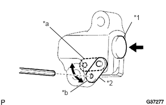
Move the stopper plate upward to release the lock, and push the plunger deep into the No. 1 timing chain tensioner assembly.
| *1 | Plunger |
| *2 | Stopper Plate |
| *a | Upward |
| *b | Downward |
Move the stopper plate downward to set the lock, and insert a 1.27 mm hexagon wrench into the hole on the stopper plate.
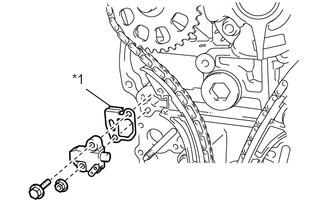
Install a new gasket and the No. 1 timing chain tensioner assembly with the bolt and nut.
- Torque:
10 N*m (102 kgf*cm, 7 ft.*lbf)
| *1 | Gasket |
Remove the hexagon wrench.
13566B
50.INSTALL TIMING CHAIN GUIDE
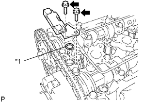
Install a new O-ring and the timing chain guide with the 2 bolts.
- Torque:
10 N*m (102 kgf*cm, 7 ft.*lbf)
| *1 | O-ring |
15131
51.INSTALL OIL PUMP RELIEF VALVE
16100
52.INSTALL WATER PUMP ASSEMBLY
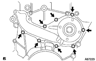
Install a new gasket and the water pump assembly with the 8 bolts.
- Torque:
8.9 N*m (91 kgf*cm, 79 in.*lbf)
11301C
53.INSTALL TIMING GEAR CASE OR TIMING CHAIN CASE OIL SEAL
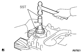
Place the timing chain or belt cover sub-assembly on wooden blocks.
Using SST and hammer, tap in the oil seal until its surface is flush with the timing chain or belt cover sub-assembly edge.
- SST
- 09223-75010
09950-70010 (09951-07100)
- NOTICE:
- ·
Keep the lip free from foreign matter.
·Do not tap the timing chain or belt cover sub-assembly or timing chain case oil seal at an angle.
Apply a light coat of MP grease to a new oil seal lip.
11302
54.INSTALL TIMING CHAIN OR BELT COVER SUB-ASSEMBLY
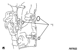
Install 3 new O-rings onto the timing chain or belt cover sub-assembly as shown in the illustration.
| *1 | O-ring |
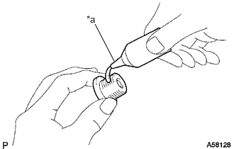
Apply adhesive to the timing chain cover plug.
- Adhesive:
Toyota Genuine Adhesive 1324, Three Bond 1324 or equivalent
| *a | Adhesive 1324 |
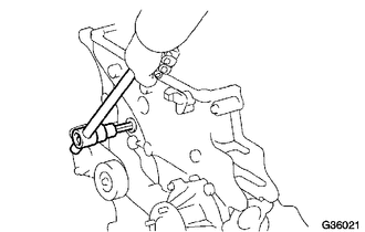
Using a 10 mm socket hexagon wrench, install the timing chain cover plug.
- Torque:
17 N*m (170 kgf*cm, 12 ft.*lbf)
Apply seal packing in a continuous line as shown in the illustration.
- Seal packing:
Toyota Genuine Seal Packing Black, Three Bond 1207B or equivalent
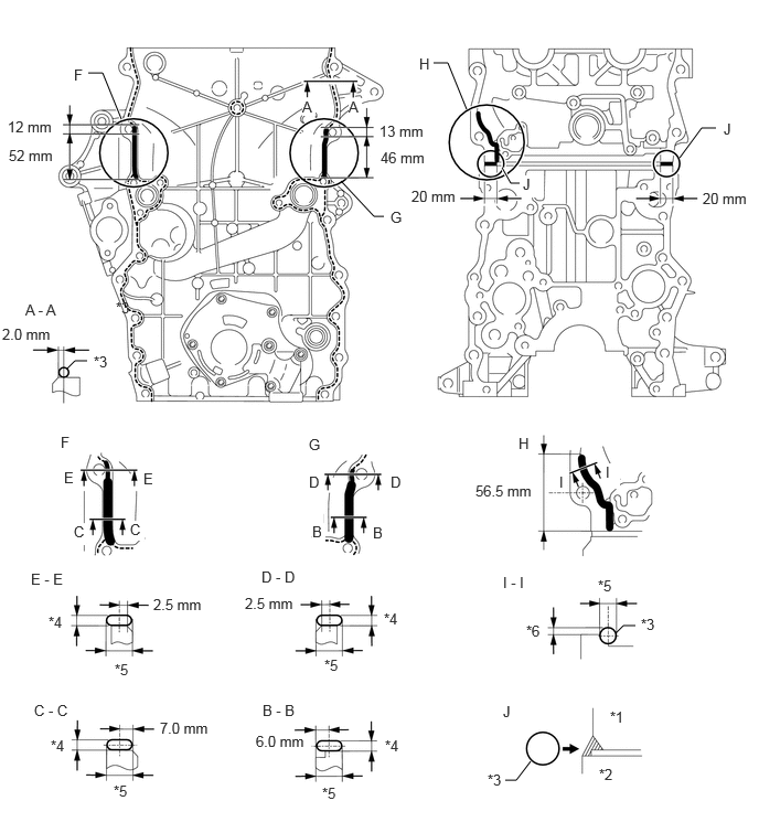
| *1 | Cylinder Head | *2 | Cylinder Block |
| *3 | Seal Packing | *4 | Seal Packing Thickness |
| *5 | Seal Packing Width | *6 | Protrusion |
- Application Specification:
Area Seal Packing Diameter Distance from Edge of Cover to Center of Seal Packing Seal Packing Application Length Protrusion from Cylinder Head A - A
(Dashed line)2.5 to 4.0 mm (0.0984 to 0.157 in.) 2.0 mm (0.0787 in.) - - B - B
(Continuous line)12 to 16 mm (0.472 to 0.630 in.) wide and 2.5 to 4.0 mm (0.0984 to 0.157 in.) thick 6.0 mm (0.236 in.) 36 mm (1.42 in.) from top of bolt hole - C - C
(Continuous line)10 to 14 mm (0.394 to 0.551 in.) wide and 2.5 to 4.0 mm (0.0984 to 0.157 in.) thick 7.0 mm (0.276 in.) 52 mm (2.05 in.) from top of bolt hole - D - D
(Continuous line)9.0 to 13 mm (0.354 to 0.512 in.) wide and 2.5 to 4.0 mm (0.0984 to 0.157 in.) thick - 12 mm (0.472 in.) from top of bolt hole - E - E
(Continuous line)9.0 to 13 mm (0.354 to 0.512 in.) wide and 2.5 to 4.0 mm (0.0984 to 0.157 in.) thick - 12 mm (0.472 in.) from top of bolt hole - I - I
(Continuous line)8.0 mm (0.315 in.) - 56.5 mm (2.22 in.) from bottom of cylinder head 2.0 to 3.0 mm (0.0787 to 0.118 in.) J 8.0 mm (0.315 in.) - 20 mm (0.787 in.) -
- NOTICE:
- ·
Remove any oil from the contact surface.
·Install the timing chain or belt cover sub-assembly within 3 minutes and tighten the bolts within 15 minutes of applying the seal packing.
·Do not start the engine for at least 4 hours after installing.
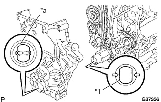
Align the oil pump drive rotor spline and the crankshaft as shown in the illustration. Install the spline and chain cover onto the crankshaft.
| *1 | Crankshaft |
| *a | Drive Rotor Spline |
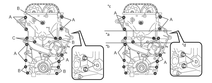
Temporarily install the timing chain cover with the 18 bolts and nut.
- NOTICE:
- ·
Do not put any oil to the bolt treads.
·Remove any oil from the bolts and bolt holes.
Excluding bolt A, tighten the bolts and nut in this order: Area 1, Area 2, Area 3.
- Torque:
23 N*m (235 kgf*cm, 17 ft.*lbf)
- HINT:
-
Bolt length:
-
75 mm (2.95 in.) for bolt A
-
75 mm (2.95 in.) for bolt B
-
90 mm (3.54 in.) for bolt C
Tighten the bolts labeled A in this order: Area 2 and Area 3.
- Torque:
57 N*m (581 kgf*cm, 42 ft.*lbf)
Tighten the bolts labeled D for Area 4.
- Torque:
21 N*m (214 kgf*cm, 15 ft.*lbf)
- HINT:
-
Bolt length:
-
40 mm (1.57 in.) for bolt D
12101
55.INSTALL OIL PAN SUB-ASSEMBLY
Install the stud bolt.
Using an E7 "TORX" socket wrench, install the stud bolts labeled A for the oil strainer as shown in the illustration.
- Torque:
7.5 N*m (76 kgf*cm, 66 in.*lbf)
Using an E5 "TORX" socket wrench, install the stud bolts labeled B for the oil pan as shown in the illustration.
- Torque:
3.0 N*m (31 kgf*cm, 27 in.*lbf)
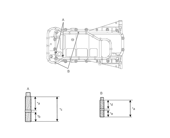
| *a | 18 mm (0.709 in. ) | *b | 13 mm (0.512 in. ) |
| *c | 33 mm (1.299 in. ) | *d | 8.5 mm (0.335 in. ) |
| *e | 8.0 mm (0.315 in. ) | - | - |
Install a new tight plug.
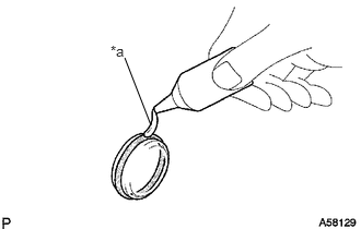
Apply adhesive around a new tight plug.
- Adhesive:
Toyota Genuine Adhesive 1324, Three Bond 1324 or equivalent
| *a | Adhesive 1324 |
- NOTICE:
-
Install the tight plug within 3 minutes after applying adhesive.
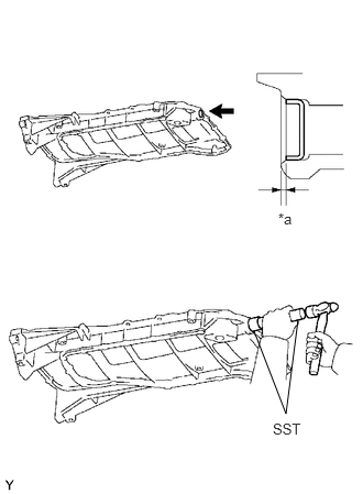
Using SST and a hammer, tap in the tight plug as shown in the illustration.
- SST
- 09950-70010 (09951-07100)
| *a | 1.5 mm(0.256 in.) |
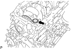
Install a new O-ring.
Apply seal packing in a continuous line, as shown in the illustration.
- Standard seal diameter:
2 to 3 mm (0.08 to 0.12 in.)
- Seal packing:
Toyota Genuine Seal Packing Black, Three Bond 1207B or equivalent
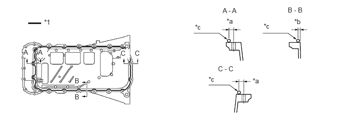
| *1 | Seal Packing | - | - |
| *a | 8.0 mm(0.315 in.) | *b | 6.5 mm(0.256 in.) |
| *c | Seal Diameter
2.0 to 3.0 mm(0.079 to 0.118 in.) |
- | - |
- NOTICE:
- ·
Remove any oil from the contact surface.
·Install the crankcase within 3 minutes of applying the seal packing.
·Do not start the engine for at least 4 hours after installing.
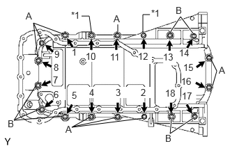
Temporarily install the oil pan sub-assembly with the 16 bolts and 2 nuts.
| *1 | Nut |
- HINT:
-
Bolt length:
for Bolt A 20 mm (0.79 in.) for Bolt B 40 mm (1.57 in.)
Uniformly tighten the 16 bolts and 2 nuts in the sequence shown in the illustration.
- Torque:
26 N*m (265 kgf*cm, 19 ft.*lbf)
15104
56.INSTALL OIL STRAINER SUB-ASSEMBLY
Install a new gasket and the oil strainer sub-assembly with the bolt and 2 nuts.
- Torque:
26 N*m (265 kgf*cm, 19 ft.*lbf)
12102A
57.INSTALL NO. 2 OIL PAN SUB-ASSEMBLY
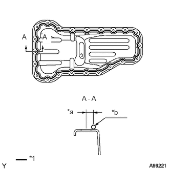
Apply seal packing in a continuous line, as shown in the illustration.
- Standard seal diameter:
2.5 to 3.5 mm (0.098 to 0.138 in.)
- Seal packing:
Toyota Genuine Seal Packing Black, Three Bond 1207B or equivalent
| *1 | Seal Packing |
| *a | 6.0 mm (0.236 in.) |
| *b | Seal Diameter
2.5 to 3.5 mm (0.098 to 0.138 in.) |
- NOTICE:
- ·
Remove any oil from the contact surface.
·Install the No. 2 oil pan sub-assembly within 3 minutes of applying the seal packing.
·Do not start the engine for at least 4 hours after installing.
Temporarily install the No. 2 oil pan sub-assembly with the 20 bolts and 2 nuts.
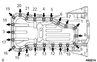
Uniformly tighten the 20 bolts and 2 nuts in the sequence shown in the illustration.
- Torque:
9.0 N*m (92 kgf*cm, 80 in.*lbf)
Install a new gasket and the drain plug.
13471
58.INSTALL CRANKSHAFT PULLEY SUB-ASSEMBLY
Align the pulley set key with the key groove of the crankshaft pulley sub-assembly, and slide on the pulley.
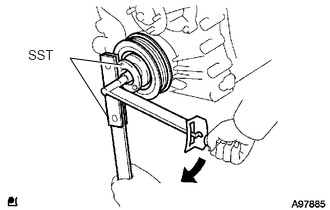
Using SST, install a new bolt.
- SST
- 09213-54015
09330-00021
- Torque:
260 N*m (2651 kgf*cm, 192 ft.*lbf)
- NOTICE:
-
Do not reuse the bolt.
11201
59.INSTALL CYLINDER HEAD COVER SUB-ASSEMBLY
Install the new cylinder head gasket and new No. 2 cylinder head gasket onto the cylinder head cover sub-assembly.
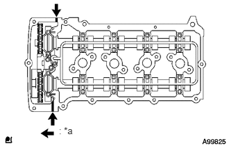
Apply seal packing to the places shown in the illustration.
- Seal packing:
Toyota Genuine Seal Packing Black, Three Bond 1207B or equivalent
| *a | Seal Packing |
- NOTICE:
- ·
Remove any oil from the contact surface.
·Install the cylinder head cover sub-assembly within 3 minutes of applying the seal packing.
·Do not start the engine for at least 2 hours after installing.
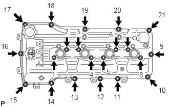
Temporarily install the cylinder head cover sub-assembly with the 19 bolts and 2 nuts.
Uniformly tighten the 19 bolts and 2 nuts in the sequence shown in the illustration.
- Torque:
9.0 N*m (92 kgf*cm, 80 in.*lbf)
12204
60.INSTALL VENTILATION VALVE SUB-ASSEMBLY
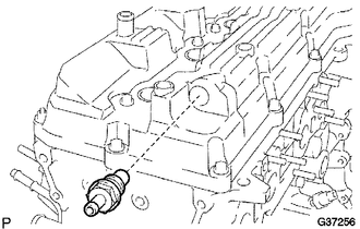
Install the ventilation valve sub-assembly onto the cylinder head cover sub-assembly.
- Torque:
5.0 N*m (51 kgf*cm, 44 in.*lbf)
12108
61.INSTALL OIL FILLER CAP SUB-ASSEMBLY
Install the oil filler cap sub-assembly.
19100P
62.INSTALL SPARK PLUG
Install the 4 spark plugs.
- Torque:
18 N*m (184 kgf*cm, 13 ft.*lbf)
11101J
63.INSTALL CAMSHAFT TIMING OIL CONTROL VALVE ASSEMBLY
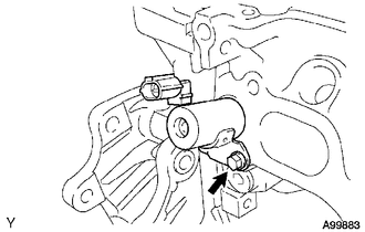
Apply a coat of engine oil to a new O-ring.
Install the camshaft timing oil control valve assembly with the bolt.
- Torque:
9.0 N*m (92 kgf*cm, 80 in.*lbf)
11301K
64.INSTALL CRANK POSITION SENSOR
Install the crankshaft position sensor with the bolt.
- Torque:
9.0 N*m (92 kgf*cm, 80 in.*lbf)
Engage the wire harness clamp.
11301M
65.INSTALL CAMSHAFT POSITION SENSOR
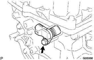
Apply a coat of engine oil to a new O-ring.
Install the new O-ring onto the camshaft position sensor.
Install the camshaft position sensor with the bolt.
- Torque:
9.0 N*m (92 kgf*cm, 80 in.*lbf)
89615
66.INSTALL KNOCK SENSOR
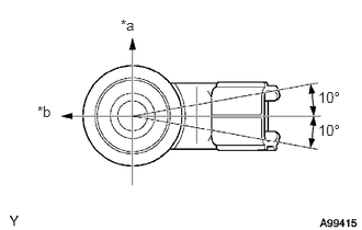
Install the knock sensor so that it is horizontal as shown in the illustration. Then install the bolt.
- Torque:
20 N*m (204 kgf*cm, 15 ft.*lbf)
| *a | Upper |
| *b | Front |
- HINT:
-
It is acceptable for the knock sensor to be tilted within 10° in either vertical direction.
83530
67.INSTALL ENGINE OIL PRESSURE SWITCH ASSEMBLY
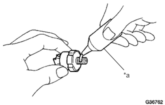
Apply adhesive to 2 or 3 threads of the engine oil pressure switch assembly.
- Adhesive:
Toyota Genuine Adhesive 1344, Three Bond 1344 or equivalent.
| *a | Adhesive 1344 |
Using a 24 mm deep socket wrench, install the engine oil pressure switch assembly.
- Torque:
15 N*m (153 kgf*cm, 11 ft.*lbf)
- NOTICE:
- ·
Install the engine oil pressure switch assembly within 3 minutes after applying adhesive.
·Do not start the engine for at least 1 hour after installation.
16331A
68.INSTALL THERMOSTAT
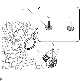
Install a new gasket onto the thermostat.
| *1 | Gasket |
| *a | CORRECT |
| *b | INCORRECT |
| *c | Upward |
| *d | 10° |
- HINT:
-
When installing the thermostat into the gasket, be careful not to deform the gasket. Make sure that the thermostat is properly installed into the groove of the gasket, as shown in the illustration.
Insert the thermostat into the cylinder block with the jiggle valve facing straight upward.
- HINT:
-
The jiggle valve may be set within 10°of either side of the prescribed position.
16321
69.INSTALL WATER INLET
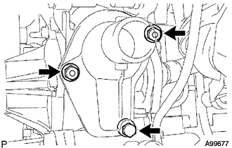
Install a new gasket.
Install the water inlet with the 2 nuts and bolt.
- Torque:
28 N*m (289 kgf*cm, 21 ft.*lbf)
16620D
70.INSTALL V-RIBBED BELT TENSIONER ASSEMBLY
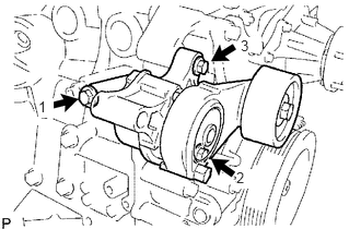
Temporarily install the V-ribbed belt tensioner assembly with the 3 bolts.
- HINT:
-
Make sure that the bolt flanges are contacting the V-ribbed belt tensioner assembly surface.
Install the V-ribbed belt tensioner assembly by tightening the 3 bolts in the order shown in the illustration.
- Torque:
- Bolt 1:
40 N*m (408 kgf*cm, 30 ft.*lbf)
- Bolt 2:
23 N*m (235 kgf*cm, 17 ft.*lbf)
- Bolt 3:
43 N*m (438 kgf*cm, 32 ft.*lbf)
12282D
71.INSTALL ENGINE HANGER
Install the 2 engine hangers with the 2 bolts.
- Torque:
42 N*m (428 kgf*cm, 31 ft.*lbf)