2TR-FE ENGINE MECHANICAL ENGINE UNIT INSPECTION
PROCEDURE

 15708
1.INSPECT NO. 1 OIL NOZZLE SUB-ASSEMBLY
Check the No. 1 oil nozzle sub-assembly for damage or clogging.
If necessary, replace the No. 1 oil nozzle sub-assembly.
13506
2.INSPECT CHAIN SUB-ASSEMBLY
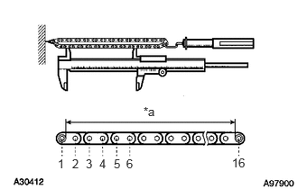
Pull the chain with a force of 147 N (15 kgf, 33 lbf) as shown in the illustration.
Using a vernier caliper, measure the length of 16 links.
- Maximum chain elongation:
147.5 mm (5.807 in.)
| *a | Measuring Area |
If the elongation is greater than the maximum, replace the chain sub-assembly.
- NOTICE:
-
Make the same measurement pulling at 3 or more places selected at random. Average the measurements.
13507
3.INSPECT NO. 2 CHAIN SUB-ASSEMBLY
Pull the chain with a force of 147 N (15 kgf, 33 lbf) as shown in the illustration.
Using a vernier caliper, measure the length of 16 links.
- Maximum chain elongation:
123.6 mm (4.866 in.)
| *a | Measuring Area |
If the elongation is greater than the maximum, replace the No. 2 chain sub-assembly.
- NOTICE:
-
Make the same measurement pulling at 3 or more places selected at random. Average the measurements.
13050
4.INSPECT CAMSHAFT TIMING GEAR ASSEMBLY
13511
5.INSPECT CAMSHAFT
13512
6.INSPECT NO. 2 CAMSHAFT
13540
7.INSPECT NO. 1 CHAIN TENSIONER ASSEMBLY
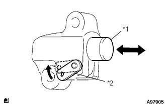
Move the stopper plate upward to release the lock. Push the plunger and check that it moves smoothly.
| *1 | Plunger |
| *2 | Stopper Plate |
13550
8.INSPECT NO. 2 CHAIN TENSIONER ASSEMBLY
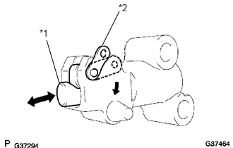
Move the stopper plate downward to release the lock.
Push the plunger and check that it moves smoothly.
| *1 | Plunger |
| *2 | Stopper Plate |
13523
9.INSPECT CAMSHAFT TIMING GEAR OR SPROCKET
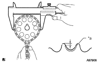
Measure the distance between the sprocket tip and the edge of the most worn area.
- Minimum distance:
1.0 mm (0.039 in.)
| *a | Worn Area |
If the distance is less than the minimum, replace the camshaft timing gear or sprocket.
- HINT:
-
If the worn area is too small or difficult to distinguish from a normal area, perform the steps below.
Wrap the chain around the sprocket.
Using a vernier caliper, measure the sprocket diameter with the chain.
- Minimum sprocket diameter (with chain):
113.8 mm (4.480 in.)
- HINT:
-
The vernier caliper must contact the chain rollers for the measurement.
If the diameter is less than the minimum, replace the chain sub-assembly and camshaft timing gear or sprocket.
13050
10.INSPECT CAMSHAFT TIMING GEAR ASSEMBLY
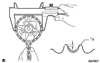
Measure the distance between the sprocket tip and the edge of the most worn area.
- Minimum distance:
1.0 mm (0.039 in.)
| *a | Worn Area |
If the distance is less than the minimum, replace the camshaft timing gear assembly.
- HINT:
-
If the worn area is too small or difficult to distinguish from a normal area, perform the steps below.
Wrap the chain around the camshaft timing gear assembly.
Using a vernier caliper, measure the sprocket diameter with the chain.
- Minimum sprocket diameter (with chain):
113.8 mm (4.480 in.)
- HINT:
-
The vernier caliper must contact the chain rollers for the measurement.
If the diameter is less than the minimum, replace the chain sub-assembly and camshaft timing gear assembly.
13597
11.INSPECT NO. 2 CRANKSHAFT TIMING SPROCKET
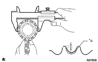
Measure the distance between the sprocket tip and the edge of the most worn area.
- Minimum distance:
1.0 mm (0.039 in.)
| *a | Worn Area |
If the distance is less than the minimum, replace the No. 2 crankshaft timing sprocket.
- HINT:
-
If the worn area is too small or difficult to distinguish from a normal area, perform the steps below.
Wrap the chain around the No. 2 crankshaft timing sprocket.
Using a vernier caliper, measure the sprocket diameter with the chain.
- Minimum sprocket diameter (with chain):
59.4 mm (2.358 in.)
- HINT:
-
The vernier caliper must contact the chain rollers for the measurement.
If the diameter is less than the minimum, replace the chain sub-assembly and No. 2 crankshaft timing sprocket.
13559
12.INSPECT CHAIN TENSIONER SLIPPER
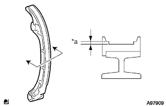
Using a vernier caliper, measure the chain tensioner slipper wear.
- Maximum wear:
2.0 mm (0.079 in.)
| *a | Wear |
If the wear is greater than the maximum, replace the chain tensioner slipper.
13561
13.INSPECT NO. 1 CHAIN VIBRATION DAMPER
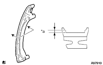
Using a vernier caliper, measure the vibration damper wear.
- Maximum wear:
2.0 mm (0.079 in.)
| *a | Wear |
If the wear is greater than the maximum, replace the No. 1 chain vibration damper.
13566B
14.INSPECT TIMING CHAIN GUIDE
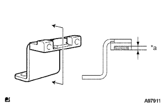
Using a vernier caliper, measure the vibration damper wear.
- Maximum wear:
0.5 mm (0.020 in.)
| *a | Wear |
If the wear is greater than the maximum, replace the timing chain guide.
13063
15.INSPECT BALANCESHAFT DRIVE GEAR SUB-ASSEMBLY
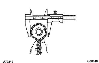
Wrap the chain around the balanceshaft drive gear sub-assembly.
Using a vernier caliper, measure the drive gear diameter with the chain.
- Minimum drive gear diameter (with chain):
75.9 mm (2.988 in.)
- HINT:
-
The vernier caliper must contact the chain rollers for the measurement.
If the diameter is less than the minimum, replace the No. 2 chain sub-assembly and balanceshaft drive gear sub-assembly.
13562
16.INSPECT NO. 2 CHAIN VIBRATION DAMPER
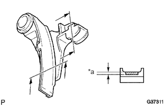
Using a vernier caliper, measure the No. 2 chain vibration damper wear.
- Maximum wear:
1.0 mm (0.039 in.)
| *a | Wear |
If the wear is greater than the maximum, replace the No. 2 chain vibration damper.
13563
17.INSPECT NO. 3 CHAIN VIBRATION DAMPER
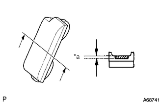
Using a vernier caliper, measure the No. 3 chain vibration damper wear.
- Maximum wear:
1.0 mm (0.039 in.)
| *a | Wear |
If the wear is greater than the maximum, replace the No. 3 chain vibration damper.
13554
18.INSPECT NO. 4 CHAIN VIBRATION DAMPER
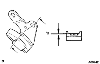
Using a vernier caliper, measure the No. 4 chain vibration damper wear.
- Maximum wear:
1.0 mm (0.039 in.)
| *a | Wear |
If the wear is greater than the maximum, replace the No. 4 chain vibration damper.
11101A
19.INSPECT CYLINDER HEAD SET BOLT
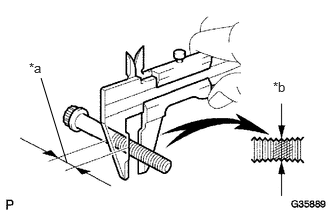
Using a vernier caliper, measure the minimum diameter of the elongated thread at the measuring point.
- Standard outside diameter:
10.76 to 10.97 mm (0.4236 to 0.4319 in.)
- Minimum outside diameter:
10.40 mm (0.4094 in.)
| *a | Measuring point |
| *b | Elongated Thread |
- HINT:
-
If a visual check reveals no excessively thin areas, check the center of the bolt (see illustration) and find the area that has the lowest diameter.
If the diameter is less than the minimum, replace the cylinder head set bolt.
13750
20.INSPECT VALVE LASH ADJUSTER ASSEMBLY
21.INSPECT CYLINDER HEAD FOR FLATNESS
Using a precision straightedge and feeler gauge, measure the surface contacting the cylinder block and manifold for warpage.
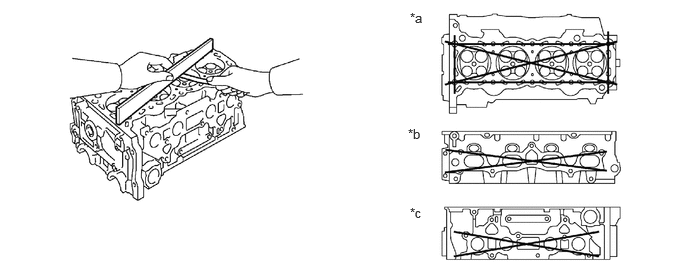
- Maximum warpage:
0.05 mm (0.0020 in.)
| *a | Cylinder Block Side | *b | Intake Manifold Side |
| *c | Exhaust Manifold Side | - | - |
If the warpage is greater than the maximum, replace the cylinder head sub-assembly.
22.INSPECT CYLINDER HEAD FOR CRACKS
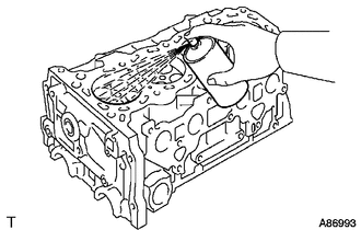
Using a dye penetrant, check the intake ports, exhaust ports and cylinder surface for cracks.
If cracked, replace the cylinder head sub-assembly.
11131
23.INSPECT INTAKE VALVE SEAT
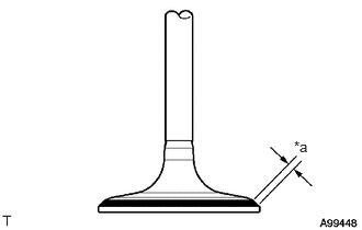
Apply a light coat of Prussian blue to the valve face.
Lightly press the valve face against the valve seat.
Check the valve face and valve seat according to the following procedures:
If blue appears 360° around the valve face, the valve face is concentric. If not, replace the intake valve.
If blue appears 360° around the valve seat, the guide and valve face are concentric. If not, resurface the valve seat.
Check that the valve seat contact is in the middle of the valve face with the width between 1.0 and 1.4 mm (0.039 and 0.055 in.).
| *a | Width |
11135
24.INSPECT EXHAUST VALVE SEAT
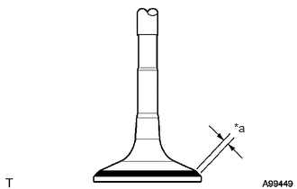
Apply a light coat of Prussian blue to the valve face.
Lightly press the valve face against the valve seat.
Check the valve face and valve seat according to the following procedures:
If blue appears 360° around the valve face, the valve face is concentric. If not, replace the exhaust valve.
If blue appears 360° around the valve seat, the guide and valve face are concentric. If not, resurface the valve seat.
Check that the valve seat contact is in the middle of the valve face with the width between 1.0 and 1.4 mm (0.039 and 0.055 in.).
| *a | Width |
25.INSPECT CAMSHAFT THRUST CLEARANCE
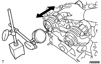
Using a dial indicator, measure the thrust clearance while moving the camshaft back and forth.
- Standard thrust clearance:
0.10 to 0.24 mm (0.004 to 0.009 in.)
- Maximum thrust clearance:
0.26 mm (0.010 in.)
If the thrust clearance is greater than the maximum, replace the cylinder head. If the thrust surface is damaged, replace the camshaft.
26.INSPECT CAMSHAFT OIL CLEARANCE
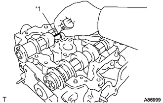
Clean the bearing caps and camshaft journals.
Place the camshafts on the cylinder head.
Lay a strip of Plastigage across each of the camshaft journals.
| *1 | Plastigage |
Install the bearing caps.
Click hereEngine / Hybrid System>2TR-FE (ENGINE MECHANICAL)>ENGINE UNIT>REASSEMBLY
- NOTICE:
-
Do not turn the camshaft.
Remove the bearing caps.
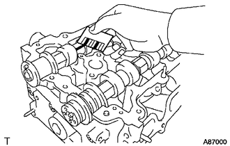
Measure the Plastigage at its widest point.
- Standard oil clearance:
Item Specified Condition No. 1 journal 0.035 to 0.072 mm (0.0014 to 0.0029 in.) Other journal 0.025 to 0.062 mm (0.0010 to 0.0028 in.)
- Maximum oil clearance:
0.08 mm (0.0031 in.)
If the oil clearance is greater than the maximum, replace the camshaft. If necessary, replace the cylinder head sub-assembly.
Completely remove the Plastigage.
13711B
27.INSPECT COMPRESSION SPRING
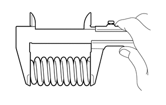
Using a vernier caliper, measure the free length of the compression spring.
- Standard free length:
52.13 mm (2.0524 in.)
If the free length is not as specified, replace the compression spring.
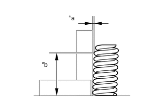
Using a steel square and feeler gauge, measure the deviation of the outer compression spring as shown in the illustration.
- Maximum deviation:
1.3 mm (0.0512 in.)
- Maximum angle (reference):
2°
| *a | Deviation |
| *b | 35 mm (1.38 in. ) |
If the deviation is greater than the maximum, replace the compression spring.
13711
28.INSPECT INTAKE VALVE
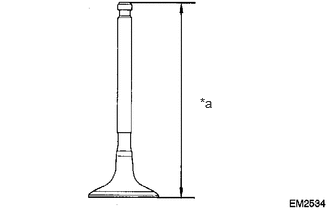
Using a vernier caliper, measure the overall valve length.
- Standard overall length:
106.26 mm (4.1835 in.)
- Minimum overall length:
105.96 mm (4.1716 in.)
| *a | Overall Length |
If the overall length is less than the minimum, replace the intake valve.
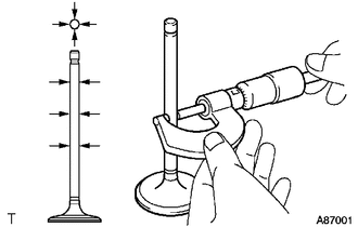
Using a micrometer, measure the diameter of the valve stem.
- Standard valve stem diameter:
5.470 to 5.485 mm (0.2154 to 0.2159 in.)
If the result is not as specified, replace the intake valve.
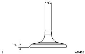
Using a vernier caliper, measure the valve head margin thickness.
- Standard margin thickness:
1.05 to 1.45 mm (0.0413 to 0.0571 in.)
- Minimum margin thickness:
0.50 mm (0.0197 in.)
| *a | Margin Thickness |
If the margin thickness is less than the minimum, replace the intake valve.
13715
29.INSPECT EXHAUST VALVE
Using a vernier caliper, measure the valve's overall length.
- Standard overall length:
106.74 mm (4.2024 in.)
- Minimum overall length:
106.44 mm (4.1905 in.)
| *a | Overall Length |
If the overall length is less than the minimum, replace the exhaust valve.
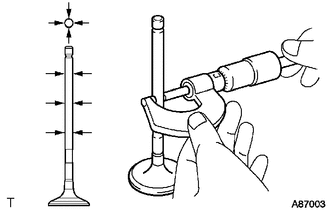
Using a micrometer, measure the diameter of the valve stem.
- Standard valve stem diameter:
5.465 to 5.480 mm (0.2151 to 0.2157 in.)
If the result is not as specified, replace the exhaust valve.
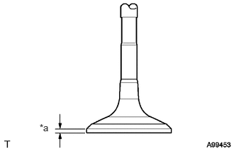
Using a vernier caliper, measure the valve head margin thickness.
- Standard margin thickness:
1.2 to 1.6 mm (0.0472 to 0.0630 in.)
- Minimum margin thickness:
0.50 mm (0.0197 in.)
| *a | Margin Thickness |
If the margin thickness is less than the minimum, replace the exhaust valve.
11122
30.INSPECT INTAKE VALVE GUIDE BUSH
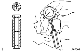
Using a caliper gauge, measure the inside diameter of the intake valve guide bush.
- Bush inside diameter:
5.510 to 5.530 mm (0.2169 to 0.2177 in.)
Subtract the valve stem diameter measurement from the intake valve guide bush inside diameter measurement.
- Standard oil clearance:
0.025 to 0.060 mm (0.0010 to 0.0024 in.)
- Maximum oil clearance:
0.08 mm (0.0032 in.)
If the clearance is greater than the maximum, replace the intake valve and intake valve guide bush.
11126
31.INSPECT EXHAUST VALVE GUIDE BUSH
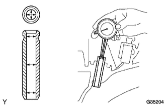
Using a caliper gauge, measure the inside diameter of the exhaust valve guide bush.
- Standard bush inside diameter:
5.510 to 5.530 mm (0.2169 to 0.2177 in.)
Subtract the valve stem diameter measurement from the guide bush inside diameter measurement.
- Standard oil clearance:
0.030 to 0.065 mm (0.0012 to 0.0026 in.)
- Maximum oil clearance:
0.10 mm (0.0039 in.)
If the clearance is greater than the maximum, replace the exhaust valve and exhaust valve guide bush.
13621
32.INSPECT NO. 1 BALANCESHAFT
Inspect the diameter of the journal.
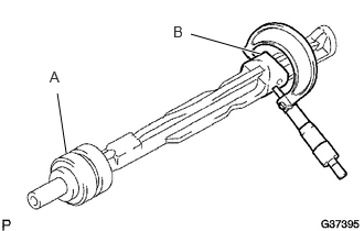
Using a micrometer, measure the diameter of the balance shaft main journals.
- Standard main journal diameter:
Item Specified Condition A 37.969 to 37.985 mm (1.4948 to 1.4955 in.) B 37.449 to 37.465 mm (1.4744 to 1.4750 in.)
Inspect the diameter of bearing.
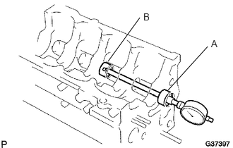
Using a cylinder gauge, measure the inside diameter of the balance shaft bearings.
- Standard bearing inside diameter:
Item Specified Condition A 38.025 to 38.045 mm (1.4970 to 1.4978 in.) B 37.525 to 37.545 mm (1.4774 to 1.4781 in.)
Inspect the oil clearance.
Subtract the balance shaft main journal diameter measurement from the balance shaft bearing inside diameter measurement.
- Standard oil clearance:
Item Specified Condition A 0.040 to 0.076 mm (0.0016 to 0.0030 in.) B 0.060 to 0.096 mm (0.0024 to 0.0038 in.)
- Maximum oil clearance:
0.15 mm (0.0059 in.)
If the oil clearance is greater than the maximum, replace the cylinder block and No. 1 balance shaft.
13622
33.INSPECT NO. 2 BALANCESHAFT
Inspect the diameter of the journal.
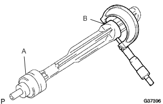
Using a micrometer, measure the diameter of the balance shaft main journals.
- Standard main journal diameter:
Item Specified Condition A 37.969 to 37.985 mm (1.4948 to 1.4955 in.) B 37.449 to 37.465 mm (1.4744 to 1.4750 in.)
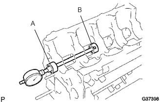
Inspect the diameter of the bearing.
Using a cylinder gauge, measure the inside diameter of the balance shaft bearings.
- Standard bearing inside diameter:
Item Specified Condition A 38.025 to 38.045 mm (1.4970 to 1.4978 in.) B 37.525 to 37.545 mm (1.4774 to 1.4781 in.)
Inspect the oil clearance.
Subtract the balance shaft main journal diameter measurement from the balance shaft bearing inside diameter measurement.
- Standard oil clearance:
Item Specified Condition A 0.040 to 0.076 mm (0.0016 to 0.0030 in.) B 0.060 to 0.096 mm (0.0024 to 0.0038 in.)
- Maximum oil clearance:
0.15 mm (0.0059 in.)
If the oil clearance is greater than the maximum, replace the cylinder block and No. 2 balance shaft.
11401
34.INSPECT CYLINDER BLOCK
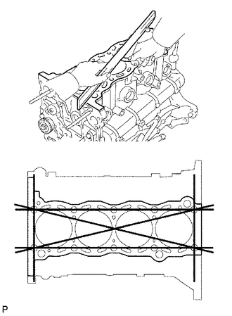
Inspect for flatness.
Using a precision straightedge and feeler gauge, measure the surface contacting the cylinder head gasket for warpage.
- Maximum warpage:
0.05 mm (0.0020 in.)
If the warpage is greater than the maximum, replace the cylinder block.
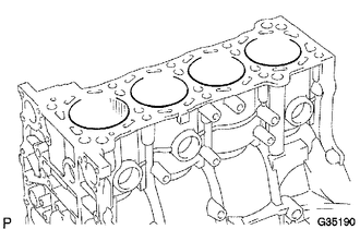
Visually check the cylinder for vertical scratches.
If deep scratches are present, rebore all 4 cylinders. If necessary, replace the cylinder block.
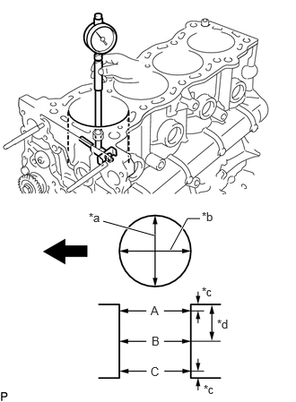
Inspect the cylinder bore diameter.
Using a cylinder gauge, measure the cylinder bore diameter at position A, B and C in the thrust and axial directions.
- Reference value (new parts):
94.990 to 95.003 mm (3.7398 to 3.7403 in.)
- Maximum diameter:
95.190 mm (3.7476 in.)
| *a | Thrust Direction |
| *b | Axial Direction |
| *c | 10 mm (0.394 in.) |
| *d | 70 mm (2.76 in.) |

|
Front |
If the diameter is more than the maximum, rebore all 4 cylinders. If necessary, replace the cylinder block.
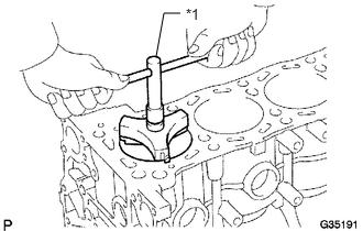
Inspect the cylinder ridge.
If the wear is less than 0.2 mm (0.008 in.), using a ridge reamer, grind the top of the cylinder block.
| *1 | Ridge Reamer |
13101
35.INSPECT PISTON WITH PIN
Inspect the piston oil clearance.
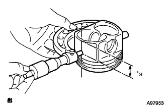
Using a micrometer, measure the piston diameter at right angles to the piston center line, at the indicated distance from the piston end.
- Standard distance:
13.8 mm (0.543 in.)
- Standard piston diameter:
Item Specified Condition Standard side 94.940 to 94.950 mm (3.7378 to 3.7382 in.) O/S 0.50 95.440 to 95.450 mm (3.7575 to 3.7579 in.)
| *a | Distance |
Measure the cylinder bore diameter in the thrust direction.
Subtract the piston diameter measurement from the cylinder bore diameter measurement.
- Standard oil clearance:
0.019 to 0.052 mm (0.0007 to 0.0020 in.)
If the oil clearance is greater than the standard, replace all 4 pistons and rebore all 4 cylinders. If necessary, replace the cylinder block.
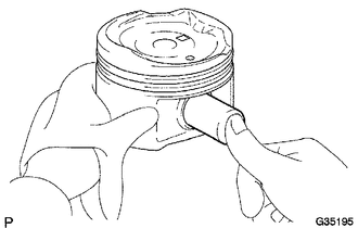
Inspect the piston pin fit.
At 60°C (140°F), check that the piston pin can be pushed into the piston pin hole with your thumb.
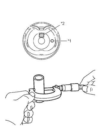
Inspect the piston pin diameter.
- HINT:
-
There are 3 piston pin sizes, which are indicated by a mark A, B, C or D on its surface.
Using a micrometer, measure the piston pin diameter.
- Standard piston pin diameter:
Mark Specified Condition A 21.997 to 22.000 mm (0.8660 to 0.8661 in.) B 22.001 to 22.003 mm (0.8662 to 0.8663 in.) C 22.004 to 22.006 mm (0.8663 to 0.8664 in.) D 22.007 to 22.009 mm (0.8664 to 0.8665 in.)
| *1 | Front Mark |
| *2 | Mark A, B, C or D |
If the diameter is not as specified, replace the piston pin and piston as a set.
13011
36.INSPECT PISTON RING SET
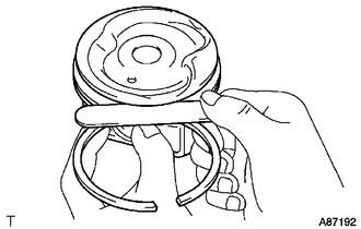
Using a feeler gauge, measure the clearance between a new piston ring and the wall of the ring groove.
- Standard ring groove clearance:
Item Specified Condition No. 1 ring 0.020 to 0.075 mm (0.0008 to 0.0030 in.) No. 2 ring 0.020 to 0.065 mm (0.0008 to 0.0026 in.) Oil ring 0.020 to 0.070 mm (0.0008 to 0.0028 in.)
If the clearance is not as specified, replace the piston.
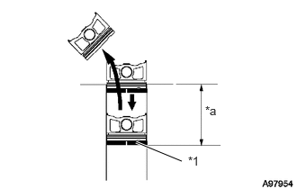
Inspect the piston ring end gap.
Insert the piston ring into the cylinder bore.
Using a piston, push the piston ring a little beyond the bottom of the ring travel, 110 mm (4.33 in.) from the top of the cylinder block.
| *1 | Piston Ring |
| *a | 110 mm (4.33 in.) |
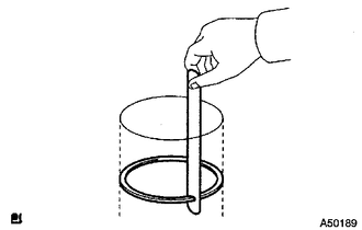
Using a feeler gauge, measure the end gap.
- Standard end gap:
Item Specified Condition No. 1 ring 0.22 to 0.34 mm (0.0087 to 0.0134 in.) No. 2 ring 0.45 to 0.57 mm (0.0177 to 0.0224 in.) Oil ring 0.10 to 0.40 mm (0.0039 to 0.0157 in.)
- Maximum end gap:
Item Specified Condition No. 1 ring 0.90 mm (0.0354 in.) No. 2 ring 1.36 mm (0.0535 in.) Oil ring 0.75 mm (0.0295 in.)
If the end gap is greater than the maximum, replace the piston ring. If the end gap is greater than the maximum, even with a new piston ring, rebore all 4 cylinders or replace the cylinder block.
13201
37.INSPECT CONNECTING ROD
Using a rod aligner and feeler gauge, check the connecting rod alignment.
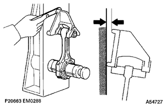
Check for bend.
- Maximum bend:
0.03 mm (0.0012 in.) per 100 mm (3.94 in.)
If the bend is greater than the maximum, replace the connecting rod.
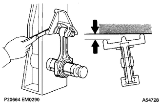
Check for twist.
- Maximum twist:
0.15 mm (0.0059 in.) per 100 mm (3.94 in.)
If the twist is greater than the maximum, replace the connecting rod.
38.INSPECT PISTON PIN OIL CLEARANCE
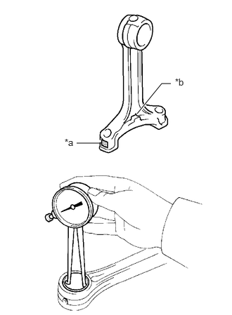
Inspect the piston pin oil clearance.
- HINT:
-
There are 3 connecting rod bush sizes, which are indicated by a mark A, B or C on its surface.
Using a caliper gauge, measure the inside diameter of the connecting rod bush.
- Standard bush inside diameter:
Mark Specified Condition A 22.005 to 22.008 mm (0.86633 to 0.86645 in.) B 22.009 to 22.011 mm (0.86649 to 0.86657 in.) C 22.012 to 22.014 mm (0.86661 to 0.86669 in.)
| *a | Mark A, B or C |
| *b | Front Mark |
If the diameter is not as specified, replace the piston pin and piston as a set.
Subtract the piston pin diameter measurement from the bush inside diameter measurement.
- Standard oil clearance:
0.001 to 0.007 mm (0.00004 to 0.00028 in.)
- Maximum oil clearance:
0.01 mm (0.00039 in.)
If the oil clearance is greater than the maximum, replace the connecting rod. If necessary, replace the piston and piston pin as a set.
13265
39.INSPECT CONNECTING ROD BOLT
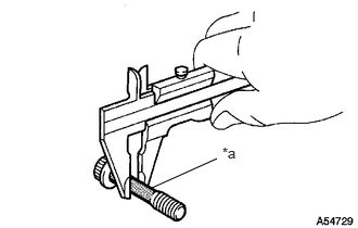
Using a vernier caliper, measure the tension portion diameter of the connecting rod bolt.
- Standard diameter:
7.2 to 7.3 mm (0.283 to 0.287 in.)
- Minimum diameter:
7.0 mm (0.276 in.)
| *a | Tension Portion |
If the diameter is less than the minimum, replace the connecting rod bolt.
13411
40.INSPECT CRANKSHAFT
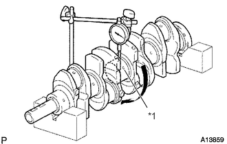
Inspect for circle runout.
Place the crankshaft on V-blocks.
Using a dial indicator, measure the circle runout at the center journal.
- Maximum circle runout:
0.03 mm (0.0012 in.)
| *1 | Center Journal |
If the circle runout is greater than the maximum, replace the crankshaft.
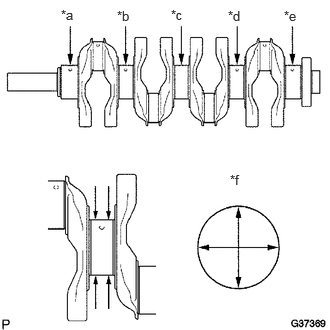
Inspect the main journals.
Using a micrometer, measure the diameter of each main journal.
- Standard journal diameter (No. 3 journal):
Mark Specified Condition 3 59.993 to 59.994 mm (2.36192 to 2.36196 in.) 4 59.991 to 59.992 mm (2.36185 to 2.36189 in.) 5 59.989 to 59.990 mm (2.36177 to 2.36181 in.) 6 59.987 to 59.988 mm (2.36169 to 2.36173 in.) 7 59.985 to 59.986 mm (2.36161 to 2.36165 in.) 8 59.983 to 59.984 mm (2.36153 to 2.36157 in.) 9 59.981 to 59.982 mm (2.36145 to 2.36149 in.)
- Standard journal diameter (Other journal):
Mark Specified Condition 0 59.999 to 60.000 mm (2.36216 to 2.36220 in.) 1 59.997 to 59.998 mm (2.36208 to 2.36212 in.) 2 59.995 to 59.996 mm (2.36200 to 2.36204 in.) 3 59.993 to 59.994 mm (2.36192 to 2.36196 in.) 4 59.991 to 59.992 mm (2.36185 to 2.36189 in.) 5 59.989 to 59.990 mm (2.36177 to 2.36181 in.) 6 59.987 to 59.988 mm (2.36169 to 2.36173 in.)
| *a | No. 1 journal |
| *b | No. 2 journal |
| *c | No. 3 journal |
| *d | No. 4 journal |
| *e | No. 5 journal |
| *f | Journal Diameter |
If the diameter is not as specified, check the oil clearance. If necessary, replace the crankshaft.
Check each main journal for taper and out-of-round as shown in the illustration.
- Maximum taper and out-of-round:
0.005 mm (0.0002 in.)
If the taper and out-of-round are greater than the maximum, replace the crankshaft.
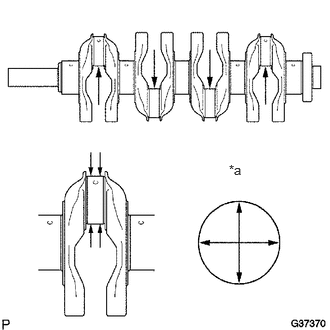
Inspect for circle runout.
Using a micrometer, measure the diameter of each crank pin.
- Standard diameter:
52.989 to 53.002 mm (2.0862 to 2.0867 in.)
| *a | Crank Pin Diameter |
If the diameter is not as specified, check the oil clearance (see "INSPECT CONNECTING ROD OIL CLEARANCE" procedures). If necessary, replace the crankshaft.
Check each crank pin for taper and out-of-round as shown in the illustration.
- Maximum taper and out-of-round:
0.003 mm (0.0001 in.)
If the taper and out-of-round are greater than the maximum, replace the crankshaft.
11416
41.INSPECT CRANKSHAFT BEARING CAP SET BOLT
Using a vernier caliper, measure the minimum diameter of the elongated thread at the measuring point.
- Standard outside diameter:
10.76 to 10.97 mm (0.4236 to 0.4319 in.)
- Minimum outside diameter:
10.66 mm (0.4197 in.)
| *a | Measuring Point |
| *b | Elongated Thread |
If the diameter is less than the minimum, replace the crankshaft bearing cap set bolt.