N04C-VL ENGINE CONTROL ECD SYSTEM P1608 Engine Lack of Power
DESCRIPTION
This DTC is stored if engine output decreases due to a malfunction in the intake or exhaust system, fuel system or cooling system. Using the GTS, the conditions present when the DTC was stored can be confirmed by referring to the freeze frame data. Freeze frame data records engine conditions when a malfunction occurs. This information can be useful when troubleshooting.
| DTC No. | DTC Detection Condition | Trouble Area |
|---|---|---|
| P1608 | With the accelerator pedal fully depressed, engine output decreases for approximately 4 to 10 seconds due to a broken component in the intake or exhaust system, fuel system or cooling system or malfunction in one of those systems.
(1 trip detection logic) |
·
Intake system clogged ·
Intake system hose disconnected or cracked ·
Turbocharger sub-assembly ·
Vacuum sensor ·
Vacuum sensor out of range ·
Atmospheric pressure sensor (built into ECM) ·
Suction control valve sticking ·
Fuel leak ·
Fuel pressure sensor (common rail assembly) ·
Engine coolant leak ·
Radiator assembly clogged ·
Water temperature sender gauge assembly ·
Water temperature sender gauge out of range or stuck ·
Fuel filter element sub-assembly ·
Injector assembly ·
Fan |
CAUTION / NOTICE / HINT
- HINT:
- ·
In contrast to normal malfunction diagnosis for components, circuits and systems, DTC P1608 is used to determine the malfunctioning area from the problem symptoms and freeze frame data when the user mentions problems such as engine lack of power or hesitation. As the DTC can be stored as a result of certain user actions, even if the DTC is output, if the customer makes no mention of problems, clear the DTC without performing any troubleshooting and return the vehicle to the customer.
·If any other DTCs are output, perform troubleshooting for those DTCs first.
·Read freeze frame data using the GTS. The ECM records vehicle and driving condition information as freeze frame data the moment a DTC is stored. When troubleshooting, freeze frame data can be helpful in determining whether the vehicle was moving or stationary, whether the engine was warmed up or not, as well as other data recorded at the time of a malfunction.
·When confirming the freeze frame data, be sure to check all 5 sets of freeze frame data.
·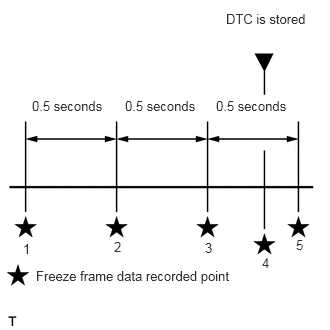 2.354,0.115 3.292,0.333 0.938,0.219 10 false DTC is stored 0.333,1.021 1.188,1.24 0.854,0.219 10 false 0.5 seconds 1.302,1.021 2.156,1.24 0.854,0.219 10 false 0.5 seconds 2.25,1.021 3.104,1.24 0.854,0.219 10 false 0.5 seconds 0.375,2.792 2.51,3.021 2.135,0.229 10 false Freeze frame data recorded point 0.24,2.51 0.396,2.708 0.156,0.198 10 false 1 1.188,2.49 1.344,2.688 0.156,0.198 10 false 2 2.135,2.5 2.292,2.698 0.156,0.198 10 false 3 2.729,2.656 2.885,2.854 0.156,0.198 10 false 4 3.083,2.469 3.24,2.667 0.156,0.198 10 false 5
The fourth set of freeze frame data is the data recorded when the DTC is stored.
PROCEDURE
Connect the GTS to the DLC3.
Turn the ignition switch to ON.
Turn the GTS on.
Enter the following menus: Powertrain / Engine and ECT / Trouble Codes.
Record the stored DTC and freeze frame data.
- HINT:
-
This freeze frame data shows the actual engine conditions when engine rack of power trouble occurred.
- Result:
Proceed to NEXT
NEXT
Connect the GTS to the DLC3.
Turn the ignition switch to ON.
Turn the GTS on.
Enter the following menus: Powertrain / Engine and ECT / Trouble Codes.
Read the DTCs.
- Result:
Result Proceed to P1608 is output A P1608 and other DTCs are output B
- HINT:
-
If any DTCs other than DTC P1608 are output, troubleshoot those DTCs first.
A
B
Determine the cause of the problem based on the freeze frame data recorded in Procedure 1.
| Judgment of Data List Values | Problem Cause | Trouble Area | Diagnosis Note |
|---|---|---|---|
| "Boost Pressure Low" in freeze frame data is ON | Actual boost pressure is lower than the target boost pressure and fuel injection volume remains suppressed. | ·
Intake system hose disconnected or cracked ·
Turbocharger sub-assembly ·
Vacuum sensor ·
Vacuum sensor out of range ·
Atmospheric pressure sensor (built into ECM) ·
Abnormal pressure difference between the atmospheric pressure sensor and vacuum sensor |
|

| Judgment of Data List Values | Problem Cause | Trouble Area | Diagnosis Note |
|---|---|---|---|
| "Common Rail Pressure Low" in freeze frame data is ON | Common rail pressure remains below the target value. | ·
Suction control valve sticking ·
Fuel leak ·
Fuel filter element sub-assembly clogged ·
Fuel pressure sensor (common rail assembly) |
|
| Judgment of Data List Values | Problem Cause | Trouble Area | Diagnosis Note |
|---|---|---|---|
| "Engine Coolant Temp High" in freeze frame data is ON | Coolant temperature remains high (overheating) and fuel injection volume remains suppressed. | ·
Engine coolant leak ·
Radiator assembly clogged ·
Water temperature sender gauge assembly ·
Water temperature sender gauge out of range or stuck ·
Fan |
Cooling system including radiator assembly |
- Result:
Proceed to NEXT
NEXT