A861E AUTOMATIC TRANSMISSION / TRANSAXLE AUTOMATIC TRANSMISSION SYSTEM P0562 System Voltage Low
DESCRIPTION
The battery power source is always supplied to the +B terminal. If there is a malfunction in the +B terminal circuit, the transmission control ECU assembly outputs a DTC.
The battery power source is supplied to the IG terminal and IG2 terminal when the ignition switch is turned to ON. If there is a malfunction in the IG terminal or IG2 terminal circuit, the transmission control ECU assembly outputs a DTC.
| DTC No. | Detection Item | DTC Detection Condition | Trouble Area | Warning Indicate | Memory |
|---|---|---|---|---|---|
| P0562 | System Voltage Low | 1. Diagnosis Condition 2. Malfunction Status 3. Malfunction Time 4. Other
DTC Detection Condition 1:
1.
Ignition switch off 2.
Engine speed is 300 rpm or more 3.
60 seconds or more 4.
1 trip detection logic DTC Detection Condition 2:
1.
0.025 seconds elapse after ignition switch is turned from off to ON 2.
Engine speed is 1500 rpm or more when transmission control ECU assembly starts 3.
3 seconds or more 4.
3 trip detection logic |
·
Wire harness or connector (+B or IG signal circuit) ·
ECU-B NO. 3 fuse ·
IGN NO. 2 fuse ·
Transmission control ECU assembly |
O/D OFF Indicator Light: Blinking | DTC stored |
CONFIRMATION DRIVING PATTERN
- HINT:
-
After the repair, clear the DTCs and perform the following procedure to check that DTCs are not output.
Start the engine and wait for at least 3 seconds.*1
Turn the ignition switch off and wait for at least 60 seconds.*2
Perform steps (*1) through (*2) 3 times.
Check for DTCs again.
WIRING DIAGRAM
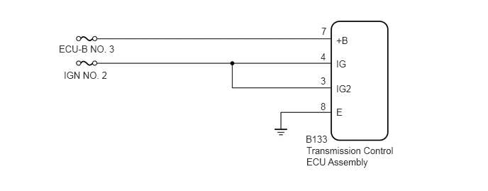
CAUTION / NOTICE / HINT
- NOTICE:
- ·
Inspect the fuses for circuits related to this system before performing the following inspection procedure.
·Perform initialization when parts related to the automatic transmission are replaced.
Click hereDrivetrain>A861E (AUTOMATIC TRANSMISSION / TRANSAXLE)>AUTOMATIC TRANSMISSION SYSTEM>INITIALIZATION
PROCEDURE
Disconnect the transmission control ECU assembly connector.
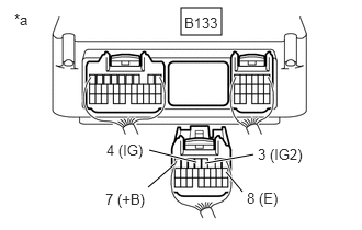
| *a | Rear view of wire harness connector
(to Transmission Control ECU Assembly) |
Measure the voltage according to the value(s) in the table below.
- Standard Voltage:
Tester Connection Condition Specified Condition B133-7 (+B) - B133-8 (E) Always 11 to 14 V B133-4 (IG) - B133-8 (E) Ignition switch ON 11 to 14 V Ignition switch off Below 1 V B133-3 (IG2) - B133-8 (E) Ignition switch ON 11 to 14 V Ignition switch off Below 1 V
- Result:
Proceed to OK NG
OK
NG