A861E AUTOMATIC TRANSMISSION / TRANSAXLE AUTOMATIC TRANSMISSION SYSTEM P2740 Transmission Fluid Temperature Sensor "B" Circuit
DESCRIPTION
The temperature sensor, which is installed to the transmission case, detects the fluid temperature inside the torque converter and in response sends a signal to the transmission control ECU assembly.
| DTC No. | Detection Item | DTC Detection Condition | Trouble Area | Warning Indicate | Memory |
|---|---|---|---|---|---|
| P2740 | Transmission Fluid Temperature Sensor "B" Circuit | 1. Diagnosis Condition 2. Malfunction Status 3. Malfunction Time 4. Other
1.
- 2.
Temperature sensor resistance is below 196 Ω or higher than 469 kΩ 3.
0.5 seconds or more 4.
1 trip detection logic |
·
Wire harness or connector (Temperature sensor signal) ·
Temperature sensor ·
Transmission control ECU assembly |
O/D OFF Indicator Light: Blinking | DTC stored |
CONFIRMATION DRIVING PATTERN
- HINT:
-
After the repair, clear the DTCs and perform the following procedure to check that DTCs are not output.
Turn the ignition switch to ON.
Check for DTCs again.
WIRING DIAGRAM
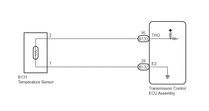
CAUTION / NOTICE / HINT
- NOTICE:
-
Perform initialization when parts related to the automatic transmission are replaced.
-
Click hereDrivetrain>A861E (AUTOMATIC TRANSMISSION / TRANSAXLE)>AUTOMATIC TRANSMISSION SYSTEM>INITIALIZATION
PROCEDURE
Disconnect the temperature sensor connector.
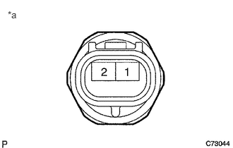
| *a | Component without harness connected
(Temperature Sensor) |
Measure the resistance according to the value(s) in the table below.
- Standard Resistance:
Tester Connection Condition Specified Condition 1 - 2 Always 196 Ω to 469 kΩ 1 - Body ground Always 10 kΩ or higher 2 - Body ground Always 10 kΩ or higher
- HINT:
-
If the resistance is out of the specified range at either of the ATF temperatures shown in the table below, the driveability of the vehicle may decrease.
ATF Temperature Specified Condition 115°C (239°F) 657 to 727 Ω 120°C (248°F) 585 to 647 Ω 145°C (293°F) 339 to 375 Ω 155°C (311°F) 278 to 308 Ω
- Result:
Proceed to OK NG
OK
NG
Disconnect the transmission control ECU assembly connector.
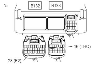
| *a | Rear view of wire harness connector
(to Transmission Control ECU Assembly) |
Measure the resistance according to the value(s) in the table below.
- Standard Resistance:
Tester Connection Condition Specified Condition B133-16 (THO) - B132-28 (E2) Always 196 Ω to 469 kΩ B133-16 (THO) - Body ground Always 10 kΩ or higher B132-28 (E2) - Body ground Always 10 kΩ or higher
- Result:
Proceed to OK NG
OK
NG