N04C-WA EMISSION CONTROL EXHAUST FUEL ADDITION INJECTOR INSTALLATION
PROCEDURE

 23710B
1.INSTALL EXHAUST FUEL ADDITION INJECTOR ASSEMBLY
- NOTICE:
- ·
During work, make sure that parts are free of foreign matter and water.
·When installing parts, make sure that part connection areas are free of foreign matter.
·After completing work, make sure to perform air bleeding, as air enters the fuel pipe during work.
Click hereEngine / Hybrid System>N04C-WA (FUEL)>FUEL SYSTEM>ON-VEHICLE INSPECTION
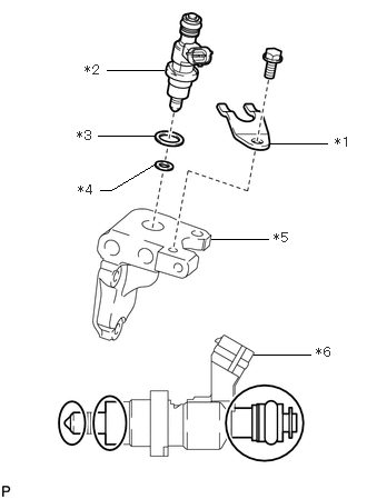
| *1 | No. 2 Nozzle Holder Clamp |
| *2 | Exhaust Fuel Addition Injector Assembly |
| *3 | O-Ring |
| *4 | Gasket |
| *5 | Exhaust Pipe |
| *6 | Connector |
Install a new gasket to the exhaust pipe.
Apply a light coat of engine oil to the new O-ring.
Install an O-ring to the exhaust pipe.
Temporarily install the exhaust fuel addition injector assembly to the exhaust pipe with the No. 2 nozzle holder clamp and bolt.
- NOTICE:
- ·
If the exhaust fuel addition injector assembly is dropped, replace it with a new one.
·Do not damage the location shown in the illustration.
·Do not allow dirt to adhere to the location shown in the illustration.
·When installing the exhaust fuel addition injector assembly, do not strongly push the connector.
·When assembling the exhaust fuel addition injector assembly, make sure that the connector is black.
- HINT:
-
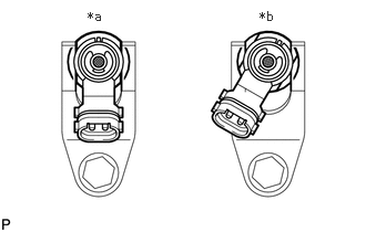 0.823,0.083 1.01,0.24 0.188,0.156 10 false *a 2.438,0.083 2.625,0.24 0.188,0.156 10 false *b
*a OK *b NG
-
Align and install the No. 2 nozzle holder clamp and exhaust fuel addition injector assembly as shown in the illustration.
Tighten the bolt.
- Torque:
- 28.5 N*m (291 kgf*cm, 21 ft.*lbf)
- NOTICE:
-
If the bolt is tightened with the No. 2 nozzle holder clamp misaligned, the No. 2 nozzle holder clamp may become deformed, so replace the No. 2 nozzle holder clamp with a new one.
23814D
2.INSTALL FUEL DELIVERY PIPE
- NOTICE:
- ·
During work, make sure that parts are free of foreign matter and water.
·When installing parts, make sure that part connection areas are free of foreign matter.
Insert the exhaust fuel addition injector assembly to the fuel delivery pipe.
Install the fuel delivery pipe to the exhaust pipe with the bolt.
- Torque:
- 28.5 N*m (291 kgf*cm, 21 ft.*lbf)
87378C
3.INSTALL EXHAUST PIPE
Install a new gasket to the front exhaust pipe assembly.
Install the exhaust pipe to the front exhaust pipe assembly with the 3 bolts and 3 washers.
- Torque:
- 28.5 N*m (291 kgf*cm, 21 ft.*lbf)
4.INSTALL OIL FILTER ELEMENT
23811H
5.CONNECT NO. 1 FUEL PIPE
Install a new gasket to the No. 1 fuel pipe.
Connect the No. 1 fuel pipe with the union bolt.
- Torque:
- 19.6 N*m (200 kgf*cm, 14 ft.*lbf)
16028
6.CONNECT NO. 2 TURBO WATER PIPE SUB-ASSEMBLY AND NO. 4 WATER BY-PASS PIPE SUB-ASSEMBLY
Install 2 new gaskets to the No. 2 turbo water pipe sub-assembly and No. 4 water by-pass pipe sub-assembly.
Connect the No. 2 turbo water pipe sub-assembly and No. 4 water by-pass pipe sub-assembly with the 2 union bolts.
- Torque:
- 24.5 N*m (250 kgf*cm, 18 ft.*lbf)
Install the clamp with the nut.
- HINT:
-
Tighten the clamp until its metal part makes contact.
Attach the wire harness clamp and connect the wire harness.
Connect the connector to the exhaust fuel addition injector assembly.
- NOTICE:
-
When connecting the connector, do not strongly push or pull the connector of the exhaust fuel addition injector.
7.ADD ENGINE COOLANT
8.INSPECT FOR COOLANT LEAK
9.BLEED AIR FROM FUEL SYSTEM
10.INSPECT FOR FUEL LEAK
11.INSPECT FOR OIL LEAK
12.INSPECT ENGINE OIL LEVEL
51405A
13.INSTALL NO. 1 ENGINE UNDER COVER SUB-ASSEMBLY