Home › Engine / Hybrid System › N04C-WA (EMISSION CONTROL) › UREA SELECTIVE CATALYTIC REDUCTION SYSTEM › from 2019.08
RM2850E _51 Engine / Hybrid System _082614 N04C-WA EMISSION CONTROL _0400651 UREA SELECTIVE CATALYTIC REDUCTION SYSTEM C

N04C-WA EMISSION CONTROL  UREA SELECTIVE CATALYTIC REDUCTION SYSTEM  U010031  Lost Communication with ECM/PCM "A" No Signal  


DESCRIPTION

The DCU (emission control ECU assembly) carries out CAN communication with the ECM via CAN circuit A (250 k).

DTC No. Detection Item DTC Detection Condition Trouble Area MIL Warning Indicate Memory
U010031 Lost Communication with ECM/PCM "A" No Signal Diagnosis Condition:
·

Ignition switch ON.

·

Battery voltage is 9 V or higher and 16 V or less.


Malfunction Status:
·

CAN communication signal from the ECM cannot be received.


Malfunction Duration:
·

4 seconds or more.


·

Harness or connector

·

ECM

·

DCU (emission control ECU assembly)

·

CAN communication system


Class A AdBlue consumption warning light:
Comes on
DTC stored

MONITOR DESCRIPTION

Description of malfunction

Blackout of CAN communication (250 k) with ECM.


Reset condition

After having restored to the normal conditions.


CONFIRMATION DRIVING PATTERN

DTC No. DTC Detection Drive Pattern
U010031 Ignition switch ON for 4 seconds or more.

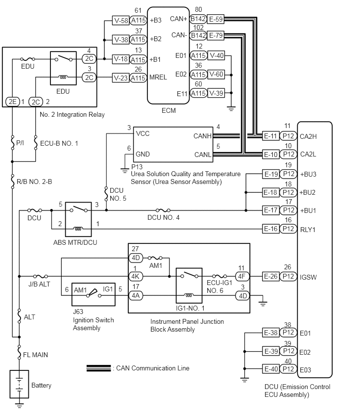
WIRING DIAGRAM

A444339E01
4.115,2.802 4.729,3 0.615,0.198 10 false CANH 6.375,2.813 6.99,3.01 0.615,0.198 10 false CA2H 3.615,0.313 4.229,0.51 0.615,0.198 10 false CAN+ 4.135,3.198 4.75,3.396 0.615,0.198 10 false CANL 6.385,3.188 7,3.385 0.615,0.198 10 false CA2L 3.646,0.656 4.26,0.854 0.615,0.198 10 false CAN- 3.438,2.26 3.865,2.469 0.427,0.208 10 false ECM 1.198,1.854 1.563,2.208 0.365,0.354 10 false EDU 2.781,3.604 5.208,4 2.427,0.396 10 false Urea Solution Quality and Temperature Sensor (Urea Sensor Assembly) 0.49,7.448 1.198,7.646 0.708,0.198 10 false FL MAIN 2.396,7.729 4.208,8.01 1.813,0.281 10 false : CAN Communication Line 0.667,8.094 1.688,8.458 1.021,0.365 10 false Battery 5.625,8.125 7.073,8.5 1.448,0.375 10 false DCU (Emission Control ECU Assembly) 1.135,5.063 2.219,5.281 1.083,0.219 10 false ABS MTR/DCU 0.583,4.542 0.948,4.74 0.365,0.198 10 false DCU 6.385,4.792 6.906,5.031 0.521,0.24 10 false RLY1 4.396,5.917 5,6.292 0.604,0.375 10 false ECU-IG1 NO. 6 6.375,5.802 6.792,5.979 0.417,0.177 10 false IGSW 6.385,3.615 6.948,3.792 0.563,0.177 10 false +BU3 6.365,4 6.917,4.188 0.552,0.188 10 false +BU2 6.385,4.385 6.833,4.604 0.448,0.219 10 false +BU1 3.177,1.552 3.573,1.76 0.396,0.208 10 false MREL 2.896,2.75 3.51,2.948 0.615,0.198 10 false VCC 2.885,3.188 3.5,3.385 0.615,0.198 10 false GND 3.74,6.458 4.469,6.656 0.729,0.198 10 false IG1-NO. 1 0.604,5.948 1.219,6.156 0.615,0.208 10 false J/B ALT 3.177,5.552 3.792,5.76 0.615,0.208 10 false AM1 1.552,6.708 2.458,7.073 0.906,0.365 10 false Ignition Switch Assembly 0.51,6.646 0.927,6.875 0.417,0.229 10 false ALT 0.354,3.771 1.417,3.99 1.063,0.219 10 false R/B NO. 2-B 3.177,1.177 3.625,1.396 0.448,0.219 10 false +B1 3.188,0.74 3.635,0.958 0.448,0.219 10 false +B2 3.188,0.344 3.635,0.563 0.448,0.219 10 false +B3 5.615,5.781 5.969,6.01 0.354,0.229 10 false E-26 6.01,5.781 6.365,6.01 0.354,0.229 10 false P12 5.063,5.781 5.271,5.979 0.208,0.198 10 false 4F 5.083,6.198 5.292,6.396 0.208,0.198 10 false 4D 2.802,6.188 3.01,6.385 0.208,0.198 10 false 4A 2.792,5.781 3,5.979 0.208,0.198 10 false 4K 2.188,6.052 2.438,6.24 0.25,0.188 10 false IG1 1.573,6.073 2,6.271 0.427,0.198 10 false AM1 3.198,6.74 4.802,7.177 1.604,0.438 10 false Instrument Panel Junction Block Assembly 1.385,6.063 1.594,6.26 0.208,0.198 10 false 6 1.865,1.375 2.073,1.573 0.208,0.198 10 false 3 2.833,5.615 3.042,5.813 0.208,0.198 10 false 1 2.813,6 3.021,6.198 0.208,0.198 10 false 17 5.063,5.604 5.271,5.802 0.208,0.198 10 false 11 5.125,6.01 5.333,6.208 0.208,0.198 10 false 3 6.042,5.583 6.25,5.781 0.208,0.198 10 false 26 6.01,2.802 6.365,3.031 0.354,0.229 10 false P12 6.021,3.188 6.375,3.417 0.354,0.229 10 false P12 6.021,3.604 6.375,3.833 0.354,0.229 10 false P12 6.01,4 6.365,4.229 0.354,0.229 10 false P12 6.021,4.375 6.375,4.604 0.354,0.229 10 false P12 6.01,4.771 6.365,5 0.354,0.229 10 false P12 6.01,6.969 6.365,7.198 0.354,0.229 10 false P12 6.021,7.365 6.375,7.594 0.354,0.229 10 false P12 6.01,7.75 6.365,7.979 0.354,0.229 10 false P12 6.375,6.99 6.896,7.229 0.521,0.24 10 false E01 6.365,7.396 6.885,7.635 0.521,0.24 10 false E02 6.375,7.771 6.896,8.01 0.521,0.24 10 false E03 5.615,2.802 5.969,3.031 0.354,0.229 10 false E-11 5.615,3.198 5.969,3.427 0.354,0.229 10 false E-10 5.625,3.615 5.979,3.844 0.354,0.229 10 false E-19 5.604,4 5.958,4.229 0.354,0.229 10 false E-18 5.615,4.375 5.969,4.604 0.354,0.229 10 false E-17 5.615,4.771 5.969,5 0.354,0.229 10 false E-16 5.615,6.979 5.969,7.208 0.354,0.229 10 false E-38 5.625,7.375 5.979,7.604 0.354,0.229 10 false E-39 5.625,7.75 5.979,7.979 0.354,0.229 10 false E-40 6.042,2.583 6.25,2.781 0.208,0.198 10 false 11 6.052,3.01 6.26,3.208 0.208,0.198 10 false 10 6.052,3.417 6.26,3.615 0.208,0.198 10 false 19 6.052,3.823 6.26,4.021 0.208,0.198 10 false 18 6.063,4.198 6.271,4.396 0.208,0.198 10 false 17 6.052,4.583 6.26,4.781 0.208,0.198 10 false 16 6.042,6.813 6.25,7.01 0.208,0.198 10 false 38 6.042,7.208 6.25,7.406 0.208,0.198 10 false 39 6.052,7.583 6.26,7.781 0.208,0.198 10 false 40 2.521,6.052 2.729,6.25 0.208,0.198 10 false 5 1.854,0.99 2.063,1.188 0.208,0.198 10 false 4 0.979,2.073 1.188,2.271 0.208,0.198 10 false 2 0.448,2.073 0.656,2.271 0.208,0.198 10 false 1 1.25,4.25 1.458,4.448 0.208,0.198 10 false 5 1.24,4.667 1.448,4.865 0.208,0.198 10 false 2 2.021,4.26 2.229,4.458 0.208,0.198 10 false 3 2.042,4.667 2.25,4.865 0.208,0.198 10 false 1 2.708,2.625 2.917,2.823 0.208,0.198 10 false 3 2.708,3.063 2.917,3.26 0.208,0.198 10 false 6 4.604,2.604 4.813,2.802 0.208,0.198 10 false 4 4.604,3.021 4.813,3.219 0.208,0.198 10 false 5 3.729,1.094 4.25,1.333 0.521,0.24 10 false E01 3.729,1.49 4.25,1.729 0.521,0.24 10 false E02 3.76,1.906 4.281,2.146 0.521,0.24 10 false E11 2.427,1.167 2.781,1.396 0.354,0.229 10 false V-18 2.438,0.76 2.792,0.99 0.354,0.229 10 false V-38 2.438,0.354 2.792,0.583 0.354,0.229 10 false V-58 4.469,1.094 4.823,1.323 0.354,0.229 10 false V-40 4.458,1.49 4.813,1.719 0.354,0.229 10 false V-60 4.458,1.896 4.813,2.125 0.354,0.229 10 false V-39 2.792,0.344 3.146,0.573 0.354,0.229 10 false A115 2.781,0.75 3.135,0.979 0.354,0.229 10 false A115 2.781,1.188 3.135,1.417 0.354,0.229 10 false A115 2.781,1.573 3.135,1.802 0.354,0.229 10 false A115 2.427,1.573 2.781,1.802 0.354,0.229 10 false V-23 2.865,0.135 3.219,0.365 0.354,0.229 10 false 61 2.875,0.573 3.229,0.802 0.354,0.229 10 false 37 2.865,0.979 3.219,1.208 0.354,0.229 10 false 13 2.865,1.385 3.219,1.615 0.354,0.229 10 false 26 4.063,1.094 4.417,1.323 0.354,0.229 10 false A115 4.156,0.896 4.365,1.094 0.208,0.198 10 false 12 4.063,1.5 4.417,1.729 0.354,0.229 10 false A115 4.063,1.896 4.438,2.125 0.375,0.229 10 false A115 4.146,1.302 4.354,1.5 0.208,0.198 10 false 36 4.146,1.698 4.354,1.896 0.208,0.198 10 false 60 4.052,0.313 4.406,0.542 0.354,0.229 10 false B142 4.063,0.667 4.417,0.896 0.354,0.229 10 false B142 4.448,0.323 4.802,0.552 0.354,0.229 10 false E-59 4.448,0.667 4.802,0.896 0.354,0.229 10 false E-79 4.146,0.115 4.354,0.313 0.208,0.198 10 false 80 4.104,0.5 4.354,0.688 0.25,0.188 10 false 102 0.344,2.948 0.583,3.125 0.24,0.177 10 false P/I 0.448,1.323 0.823,1.5 0.375,0.177 10 false EDU 0.854,2.958 1.813,3.125 0.958,0.167 10 false ECU-B NO. 1 2.333,3.958 2.76,4.302 0.427,0.344 10 false DCU NO. 5 3.135,4.531 3.948,4.74 0.813,0.208 10 false DCU NO. 4 1.552,6.531 2.167,6.74 0.615,0.208 10 false J63 2.792,3.458 3.146,3.688 0.354,0.229 10 false P13 1.813,1.563 2.021,1.76 0.208,0.198 10 false 2C 1.813,1.156 2.021,1.354 0.208,0.198 10 false 2C 0.677,2.083 0.885,2.281 0.208,0.198 10 false 2C 0.188,2.073 0.396,2.271 0.208,0.198 10 false 2E 0.844,2.344 2.396,2.542 1.552,0.198 10 false No. 2 Integration Relay 2.802,5.385 3.01,5.583 0.208,0.198 10 false 4D 2.802,5.198 3.01,5.396 0.208,0.198 10 false 27

CAUTION / NOTICE / HINT

HINT:

Read freeze frame data using the GTS. Freeze frame data records the engine condition when malfunctions are detected. When troubleshooting, freeze frame data can help determine if the vehicle was moving or stationary, if the engine was warmed up or not, and other data from the time the malfunction occurred.


PROCEDURE

1.CHECK DTC OUTPUT
a.

Connect the GTS to the DLC3.


b.

Turn the ignition switch to ON.


c.

Turn the GTS on.


d.

According to the display on the GTS, select "Health Check".


e.

Check for currently output system DTCs.

Result:
Result Proceed to
DTC U010031 is output A
2 or more of the following DTCs are simultaneously output: U010031, U02A231 and engine DTCs U010A, U010C, U010E, U029D, U029E, U02A2 and U02A3 B
DTCs are not output C


A

2.CHECK HARNESS AND CONNECTOR (ECM +B POWER SOURCE VOLTAGE)

B

C

2.CHECK HARNESS AND CONNECTOR (ECM +B POWER SOURCE VOLTAGE)
a.
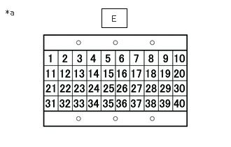
A405886C01
1.51,0.125 1.885,0.406 0.375,0.281 0.083,0.115 0.396,0.313 0.313,0.198 10 false *a 1.667,0.208 1.979,0.406 0.313,0.198 10 false E
*a Signal Check Harness Lead Connector


Connect the signal check harness to the ECM and ECM vehicle side harness.


b.

Turn the ignition switch to ON.


c.

Measure the voltage according to the value(s) in the table below.

Standard Voltage:
Tester Connection Condition Specified Condition
V-18 (+B1) - V-40 (E01) Ignition switch ON 11 to 14 V
V-38 (+B2) - V-60 (E02) Ignition switch ON 11 to 14 V
V-58(+B3) - V-39(E11) Ignition switch ON 11 to 14 V


Result:
Proceed to
OK
NG


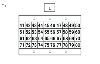
A405887C01
1.521,0.125 1.885,0.396 0.365,0.271 0.073,0.104 0.385,0.302 0.313,0.198 10 false *a 1.677,0.198 1.833,0.396 0.156,0.198 10 false E
*a Signal Check Harness Lead Connector


OK

3.CHECK HARNESS AND CONNECTOR

NG

9.GO TO ECM POWER SOURCE CIRCUIT (ECD SYSTEM)
3.CHECK HARNESS AND CONNECTOR
a.
A405886C01
1.51,0.125 1.885,0.406 0.375,0.281 0.083,0.115 0.396,0.313 0.313,0.198 10 false *a 1.667,0.208 1.979,0.406 0.313,0.198 10 false E
*a Signal Check Harness No. 2 Lead Connector


Disconnect the cable from the negative (-) battery terminal.


b.

Connect the signal check harness No. 2 to the DCU (emission control ECU assembly) vehicle side harness. (Do not connect the harness to the DCU (emission control ECU assembly).)


c.

Measure the resistance according to the value(s) in the table below.

Standard Resistance:
Tester Connection Condition Specified Condition
E-11 (CA2H) - E-10 (CA2L) Ignition switch off 54 to 69 Ω
Positive (+) battery terminal - E-11 (CA2H) Ignition switch off 6 kΩ or higher
Positive (+) battery terminal - E-10 (CA2L)
E-11 (CA2H) - Body ground Ignition switch off 200 Ω or higher
E-10 (CA2L) - Body ground


Result:
Proceed to
OK
NG


OK

4.REPLACE ECM

NG

8.REPAIR OR REPLACE HARNESS OR CONNECTOR
4.REPLACE ECM

Result:
Proceed to
NEXT


NEXT

5.CLEAR DTC
5.CLEAR DTC
a.

Connect the GTS to the DLC3.


b.

Turn the ignition switch to ON.


c.

Turn the GTS on.


d.

Clear the DTCs.

NOTICE:

Clear the DTCs with the engine stopped, as DTCs cannot be cleared while the engine is running.


e.

Turn the ignition switch off and wait for at least 30 seconds.


Result:
Proceed to
NEXT


NEXT

6.CHECK WHETHER DTC OUTPUT RECURS (DTC U010031)
a.

Drive the vehicle in accordance with the driving pattern described in the Confirmation Driving Pattern.


b.

Connect the GTS to the DLC3.


c.

Turn the ignition switch to ON.


d.

Turn the GTS on.


e.

Enter the following menus: Powertrain / Urea Selective Catalytic Reduction / Trouble Codes.


f.

Read the DTCs.

Result:
Result Proceed to
DTC U010031 is output A
DTCs are not output B


A

7.REPLACE DCU (EMISSION CONTROL ECU ASSEMBLY)

B

END

7.REPLACE DCU (EMISSION CONTROL ECU ASSEMBLY)
a.

Replace the DCU (emission control ECU assembly).

Click hereEngine / Hybrid System>N04C-WA (EMISSION CONTROL)>UREA PUMP CONTROL ECU>REMOVAL


Result:
Proceed to
NEXT


NEXT

10.CLEAR DTC
8.REPAIR OR REPLACE HARNESS OR CONNECTOR
a.

Repair or replace the harness or connector.


Result:
Proceed to
NEXT


NEXT

10.CLEAR DTC
9.GO TO ECM POWER SOURCE CIRCUIT (ECD SYSTEM)
a.

Check the ECM power source circuit (ECD system) and if there are any malfunctions, repair or replace it.

Click hereEngine / Hybrid System>N04C-WA (ENGINE CONTROL)>ECD SYSTEM>ECM Power Source Circuit


Result:
Proceed to
NEXT


NEXT

10.CLEAR DTC
10.CLEAR DTC
a.

Connect the GTS to the DLC3.


b.

Turn the ignition switch to ON.


c.

Turn the GTS on.


d.

Clear the DTCs.

NOTICE:

Clear the DTCs with the engine stopped, as DTCs cannot be cleared while the engine is running.


e.

Turn the ignition switch off and wait for at least 30 seconds.


Result:
Proceed to
NEXT


NEXT

11.CHECK WHETHER DTC OUTPUT RECURS (DTC U010031)
a.

Drive the vehicle in accordance with the driving pattern described in the Confirmation Driving Pattern.


b.

Connect the GTS to the DLC3.


c.

Turn the ignition switch to ON.


d.

Turn the GTS on.


e.

Enter the following menus: Powertrain / Urea Selective Catalytic Reduction / Trouble Codes.


f.

Read the DTCs.

OK:

DTCs are not output


Result:
Proceed to
NEXT


NEXT

END