AIR CONDITIONING CONDENSER(except 1BZ-FPE) REASSEMBLY
PROCEDURE

 1.INSTALL WIRE HARNESS CLAMP
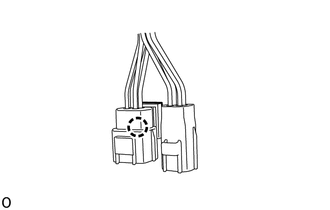
Attach the claw and install the wire harness clamp to the cooler condenser fan relay assembly.
2.INSTALL WIRE HARNESS CLAMP
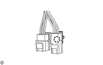
Attach the claw and install the wire harness clamp to the cooler condenser fan relay assembly.
88440C
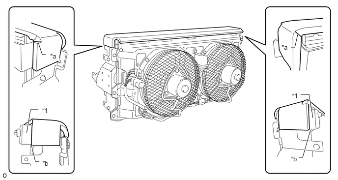
3.INSTALL COOLER CONDENSER FAN RELAY ASSEMBLY
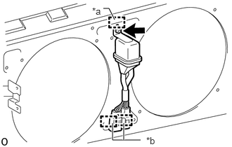
| *a | Hook |
| *b | Wire Harness Clamp |
Attach the hook and temporairly install the cooler condenser fan relay assembly.
Install the cooler condenser fan relay assembly with the bolt.
- Torque:
- 5.0 N*m (51 kgf*cm, 44 in.*lbf)
Attach the 2 wire harness clamps.
4.INSTALL PIPING CLAMP
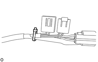
Install a new piping clamp.
88605J
5.INSTALL AIR CONDITIONING WIRING HARNESS SUB-ASSEMBLY
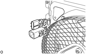
Detach the 2 claws and remove the air conditioning wiring harness sub-assembly.
88550
6.INSTALL CONDENSER BLOWER MOTOR ASSEMBLY
88454B
7.INSTALL FAN SHROUD
88453
8.INSTALL CONDENSER COOLING FAN
88550D
9.INSTALL BLOWER MOTOR ASSEMBLY
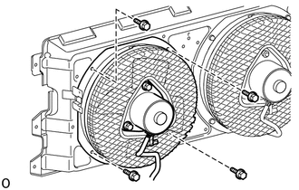
Using universal socket wrench 10 mm, install the blower motor assembly with the 4 bolts.
- HINT:
-
Use the same procedure for the other side.
- Torque:
- 5.0 N*m (51 kgf*cm, 44 in.*lbf)
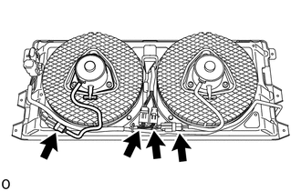
Connect the 4 connectors.
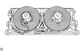
Attach the wire harness clamp.
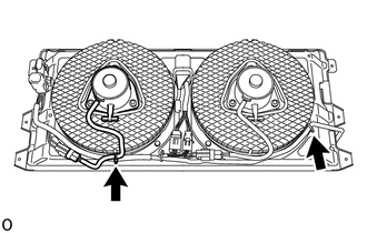
Install 2 new straps.
88461A
10.INSTALL COOLER CONDENSER CORE
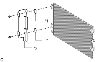
| *1 | No. 4 Cooler Condenser Bracket |
| *2 | Bracket Sub-assembly |
Install the bracket sub-assembly and 2 No. 4 cooler condenser brackets to the cooler condenser core with the 2 bolts.
- Torque:
- 5.0 N*m (51 kgf*cm, 44 in.*lbf)
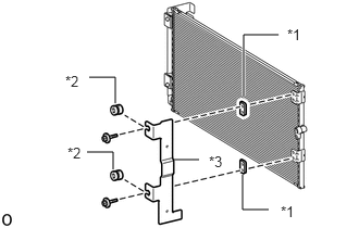
| *1 | No. 4 Cooler Condenser Bracket |
| *2 | Grommet |
| *3 | Bracket Sub-assembly |
Install the 2 grommets, bracket sub-assembly and 2 No. 4 cooler condenser brackets to the cooler condenser core with the 2 bolts.
- Torque:
- 5.0 N*m (51 kgf*cm, 44 in.*lbf)
88461C
11.INSTALL NO. 2 COOLER CONDENSER CORE
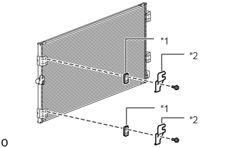
| *1 | No. 4 Cooler Condenser Bracket |
| *2 | Bracket |
Install the 2 No. 4 cooler condenser brackets and 2 brackets to the No. 2 cooler condenser core with the 2 bolts.
- Torque:
- 5.0 N*m (51 kgf*cm, 44 in.*lbf)
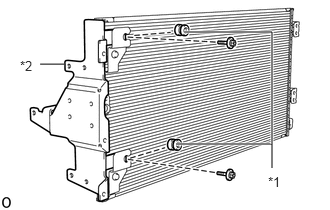
| *1 | Grommet |
| *2 | Bracket Sub-assembly |
Install the 2 grommets and the bracket sub-assembly to the No. 2 cooler condenser core with the 2 bolts.
- Torque:
- 5.0 N*m (51 kgf*cm, 44 in.*lbf)
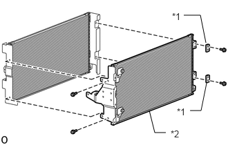
| *1 | No. 4 Cooler Condenser Bracket |
| *2 | No. 2 Cooler Condenser Core |
Install the 2 No. 4 cooler condenser brackets and No. 2 cooler condenser core to the cooler condenser core with the 4 bolts.
- Torque:
- 5.0 N*m (51 kgf*cm, 44 in.*lbf)
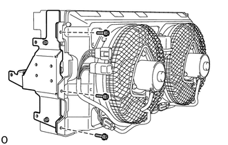
Install the fan shroud with blower assembly with the 3 bolts.
- Torque:
- 5.0 N*m (51 kgf*cm, 44 in.*lbf)
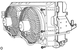
Install the bracket sub-assembly with the 3 bolts.
- Torque:
- 5.0 N*m (51 kgf*cm, 44 in.*lbf)
12.INSTALL NO. 2 COOLER PACKING
Clean the condenser assembly surface.
Remove any remaining double-sided tape from the condenser assembly.
Wipe off any tape adhesive residue with cleaner.
Heat the condenser assembly and No. 2 cooler packing using a heat light.
- CAUTION:
- ·
Do not touch the heat light and heated parts.
·Touching the heat light may result in burns.
·Touching heated parts for a long time may result in burns.
- Standard:
Item Temperature No. 2 Cooler Packing 20 to 30°C (68 to 86°F) Condenser Assembly 40 to 60°C (104 to 140°F)
Remove the peeling paper of a new No. 2 cooler packing trying not to touch the adhesional surface.
- NOTICE:
-
After removing the peeling paper, do not touch the surface of the tape with your fingers or cotton work gloves.
Align the No. 2 cooler packing as shown in the illustration.
| *1 | Bracket Sub-assembly | - | - |
| *a | No. 2 Cooler Packing Cutout | *b | Point A |
- HINT:
- ·
Align the cutout of the No. 2 cooler packing with the corner of the condenser assembly.
·Align the edge of the No. 2 cooler packing with point A of the bracket sub-assembly.
·Firmly press the No. 2 cooler packing.
88715A
13.INSTALL COOLER REFRIGERANT DISCHARGE PIPE A
Remove the vinyl tape wrapped around the connection of the cooler refrigerant discharge pipe A and No. 2 cooler condenser core.
Sufficiently apply compressor oil to a new O-ring and the fitting surface of the cooler refrigerant discharge pipe A and No. 2 cooler condenser core.
- Compressor Oil:
ND-OIL 8 or equivalent
- NOTICE:
-
Do not use any compressor oil other than ND-OIL 8 or equivalent. If any compressor oil other than ND-OIL 8 or equivalent is used, compressor motor insulation performance may decrease, resulting in leakage of electric power.
Install the O-ring to the cooler refrigerant discharge pipe A.
- NOTICE:
-
Keep the O-rings and O-ring fitting surfaces free from foreign matter.
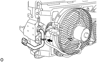
Install the cooler refrigerant discharge pipe A with the bolt.
- NOTICE:
- ·
Do not apply excessive force to the cooler refrigerant discharge pipe A.
·Make sure not to cut the O-ring while installing it. (Cut O-rings cannot be installed)
- Torque:
- 5.4 N*m (55 kgf*cm, 48 in.*lbf)
Install a new strap.
88715B
14.INSTALL COOLER REFRIGERANT DISCHARGE PIPE B
Remove the vinyl tape wrapped around the connection of the cooler refrigerant discharge pipe B, cooler refrigerant liquid pipe A and cooler condenser core.
Sufficiently apply compressor oil to 2 new O-rings and the fitting surface of the cooler refrigerant discharge pipe B, cooler refrigerant liquid pipe A and cooler condenser core
- Compressor Oil:
ND-OIL 8 or equivalent
- NOTICE:
-
Do not use any compressor oil other than ND-OIL 8 or equivalent. If any compressor oil other than ND-OIL 8 or equivalent is used, compressor motor insulation performance may decrease, resulting in leakage of electric power.
Install the 2 O-rings to the cooler refrigerant discharge pipe B.
- NOTICE:
-
Keep the O-rings and O-ring fitting surfaces free from foreign matter.
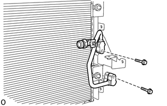
Install the cooler refrigerant discharge pipe B with the 2 bolts.
- NOTICE:
- ·
Do not apply excessive force to the cooler refrigerant discharge pipe B.
·Make sure not to cut the O-ring while installing it. (Cut O-rings cannot be installed)
- Torque:
- 5.4 N*m (55 kgf*cm, 48 in.*lbf)
15.INSTALL PIPING CLAMP
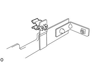
Attach the 2 claws and install the piping clamp.
88716A
16.INSTALL COOLER REFRIGERANT LIQUID PIPE A
Remove the vinyl tape wrapped around the connection of the cooler refrigerant liquid pipe A, No. 2 cooler condenser core and cooler condenser core.
Sufficiently apply compressor oil to 2 new O-rings and the fitting surface of the cooler refrigerant liquid pipe A, No. 2 cooler condenser core and cooler condenser core.
- Compressor Oil:
ND-OIL 8 or equivalent
- NOTICE:
-
Do not use any compressor oil other than ND-OIL 8 or equivalent. If any compressor oil other than ND-OIL 8 or equivalent is used, compressor motor insulation performance may decrease, resulting in leakage of electric power.
Install the 2 O-rings to the cooler refrigerant liquid pipe A.
- NOTICE:
-
Keep the O-rings and O-ring fitting surfaces free from foreign matter.
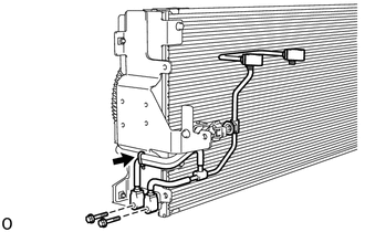
Install the cooler refrigerant liquid pipe A with the 2 bolts.
- NOTICE:
- ·
Do not apply excessive force to the cooler refrigerant liquid pipe A.
·Make sure not to cut the O-ring while installing it. (Cut O-rings cannot be installed)
- Torque:
- 5.4 N*m (55 kgf*cm, 48 in.*lbf)
Install a new strap.
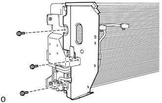
Install the dust cover with the 3 bolts.
- Torque:
- 5.0 N*m (51 kgf*cm, 44 in.*lbf)
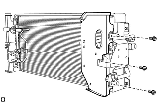
Install the dust cover with the 3 bolts.
- Torque:
- 5.0 N*m (51 kgf*cm, 44 in.*lbf)
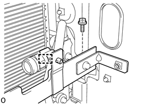
Attach the clamp and temporarily install the bracket sub-assembly.
Install the bracket sub-assembly with the bolt.
- Torque:
- 5.0 N*m (51 kgf*cm, 44 in.*lbf)
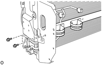
Install the 2 bolts.
- Torque:
- 5.0 N*m (51 kgf*cm, 44 in.*lbf)
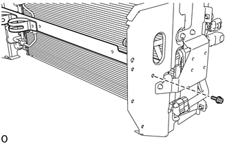
Install the bolt.
- Torque:
- 5.0 N*m (51 kgf*cm, 44 in.*lbf)
88645H
17.INSTALL NO. 1 PRESSURE SWITCH
88471
18.INSTALL RECEIVER AIR CONDITIONING TANK
88461D
19.INSTALL NO. 3 COOLER CONDENSER CORE
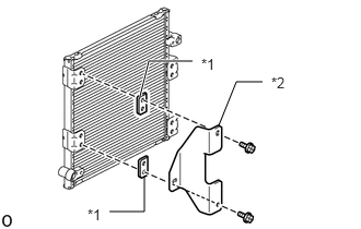
| *1 | No. 4 Cooler Condenser Bracket |
| *2 | Bracket |
Install the 2 No. 4 cooler condenser brackets and bracket to the No. 3 cooler condenser core with the 2 bolts.
- Torque:
- 5.0 N*m (51 kgf*cm, 44 in.*lbf)
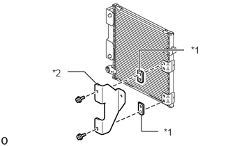
| *1 | No. 4 Cooler Condenser Bracket |
| *2 | Bracket |
Install the 2 No. 4 cooler condenser brackets and bracket to the No. 3 cooler condenser core with the 2 bolts.
- Torque:
- 5.0 N*m (51 kgf*cm, 44 in.*lbf)
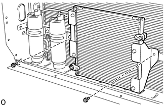
Install the No. 3 cooler condenser core with the 2 bolts.
- Torque:
- 5.0 N*m (51 kgf*cm, 44 in.*lbf)
88716B
20.INSTALL COOLER REFRIGERANT LIQUID PIPE B
Remove the vinyl tape wrapped around the connection of the cooler refrigerant liquid pipe B, receiver air conditioning tank and No. 3 cooler condenser core.
Sufficiently apply compressor oil to 3 new O-rings and the fitting surface of the cooler refrigerant liquid pipe B, receiver air conditioning tank and No. 3 cooler condenser core.
- Compressor Oil:
ND-OIL 8 or equivalent
- NOTICE:
-
Do not use any compressor oil other than ND-OIL 8 or equivalent. If any compressor oil other than ND-OIL 8 or equivalent is used, compressor motor insulation performance may decrease, resulting in leakage of electric power.
Install the 3 O-rings to the cooler refrigerant liquid pipe B.
- NOTICE:
-
Keep the O-rings and O-ring fitting surfaces free from foreign matter.
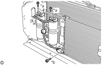
| *a | Bolt A |
| *b | Bolt B |
Install the cooler refrigerant liquid pipe B with the 3 bolts.
- NOTICE:
- ·
Do not apply excessive force to the cooler refrigerant liquid pipe B.
·Make sure not to cut the O-ring while installing it. (Cut O-rings cannot be installed)
- Torque:
- Bolt A : 5.0 N*m (51 kgf*cm, 44 in.*lbf)
- Bolt B : 5.4 N*m (55 kgf*cm, 48 in.*lbf)
88715K
21.INSTALL DISCHARGE TUBE K
Remove the vinyl tape wrapped around the connection of the refrigerant discharge pipe B and discharge tube K.
Sufficiently apply compressor oil to a new O-ring and the fitting surface of the refrigerant discharge pipe B and discharge tube K.
- Compressor Oil:
ND-OIL 8 or equivalent
- NOTICE:
-
Do not use any compressor oil other than ND-OIL 8 or equivalent. If any compressor oil other than ND-OIL 8 or equivalent is used, compressor motor insulation performance may decrease, resulting in leakage of electric power.
Install the O-ring to the discharge tube K.
- NOTICE:
-
Keep the O-rings and O-ring fitting surfaces free from foreign matter.
Using SST, tighten the nut and install the discharge tube K.
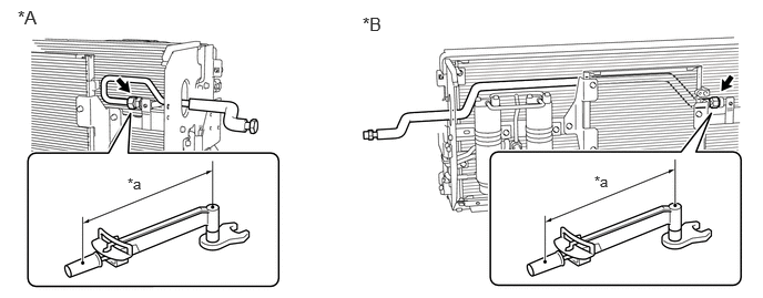
| *A | for RHD | *B | for LHD |
| *a | Torque Wrench Fulcrum Length | - | - |
- SST
- 09922-10240
- NOTICE:
- ·
Do not apply excessive force to the discharge tube K.
·Make sure not to cut the O-ring while installing it. (Cut O-rings cannot be installed)
- Torque:
- Specified tightening torque : 22.5 N*m (229 kgf*cm, 17 ft.*lbf)
- HINT:
- ·
Calculate the torque wrench reading when changing the fulcrum length of the torque wrench.
Click hereGeneral>INTRODUCTION>REPAIR INSTRUCTION>PRECAUTION
·When using SST (fulcrum length of 40 mm (1.58 in.)) + torque wrench (fulcrum length of 180 mm (7.09 in.)): 18.4 N*m (188 kgf*cm, 14 ft.*lbf)
88706
22.INSTALL LIQUID PIPE SUB-ASSEMBLY
Remove the vinyl tape wrapped around the connection of the liquid pipe sub-assembly and No. 3 cooler condenser core.
Sufficiently apply compressor oil to a new O-ring and the fitting surface of the liquid pipe sub-assembly and No. 3 cooler condenser core.
- Compressor Oil:
ND-OIL 8 or equivalent
- NOTICE:
-
Do not use any compressor oil other than ND-OIL 8 or equivalent. If any compressor oil other than ND-OIL 8 or equivalent is used, compressor motor insulation performance may decrease, resulting in leakage of electric power.
Install the O-ring to the liquid pipe sub-assembly.
- NOTICE:
-
Keep the O-rings and O-ring fitting surfaces free from foreign matter.
Install the liquid pipe sub-assembly with the bolt.
- NOTICE:
- ·
Do not apply excessive force to the liquid pipe sub-assembly.
·Make sure not to cut the O-ring while installing it. (Cut O-rings cannot be installed)
- Torque:
- Bolt A : 5.4 N*m (55 kgf*cm, 48 in.*lbf)
for RHD:
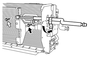

|
Bolt (A) |

|
Bolt (B) |
Install the liquid pipe sub-assembly with the bolt (B).
- NOTICE:
- ·
Do not apply excessive force to the liquid pipe sub-assembly.
·Make sure not to cut the O-ring while installing it. (Cut O-rings cannot be installed)
- Torque:
- 5.4 N*m (55 kgf*cm, 48 in.*lbf)
Move the No. 1 piping clamp in the direction shown in the illustration and install the No. 1 piping clamp with the bolt (A).
for LHD:
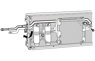
Install the liquid pipe sub-assembly with the bolt.
- NOTICE:
- ·
Do not apply excessive force to the liquid pipe sub-assembly.
·Make sure not to cut the O-ring while installing it. (Cut O-rings cannot be installed)
- Torque:
- 5.4 N*m (55 kgf*cm, 48 in.*lbf)
Move the No. 1 piping clamp in the direction shown in the illustration.
88463A
23.INSTALL NO. 2 COOLER CONDENSER BRACKET
Install the No. 2 cooler condenser bracket with the 4 bolts.
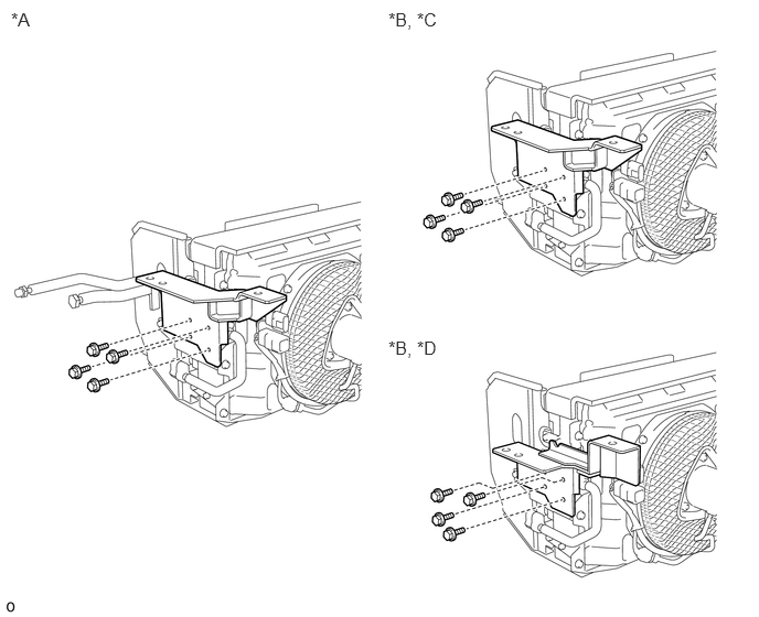
| *A | for RHD | *B | for LHD |
| *C | except Normal Body | *D | for Normal Body |
Install the 3 No. 1 cooler condenser cushions, 3 No. 2 cooler condenser cushions and 3 No. 1 condenser bracket collars.
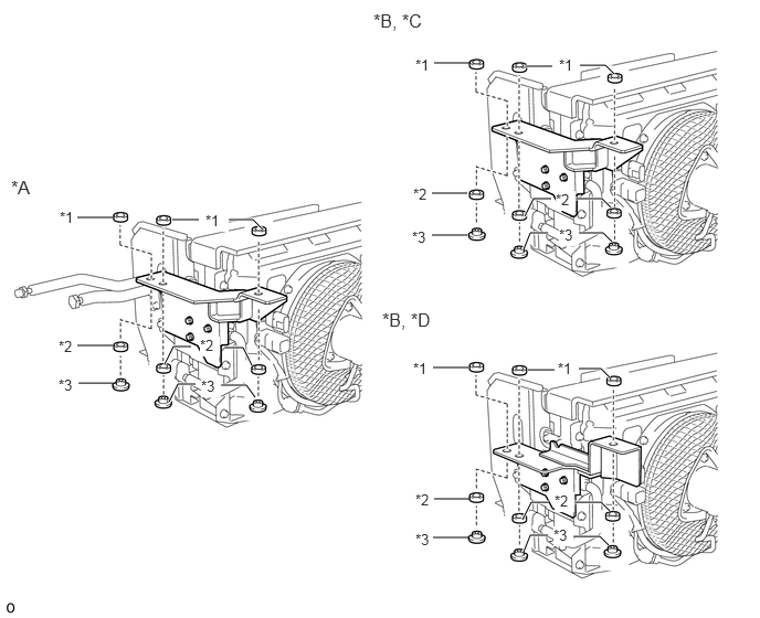
| *A | for RHD | *B | for LHD |
| *C | except Normal Body | *D | for Normal Body |
| *1 | No. 1 Cooler Condenser Cushion | *2 | No. 2 Cooler Condenser Cushion |
| *3 | No. 1 Condenser Bracket Collar | - | - |
88463B
24.INSTALL NO. 3 COOLER CONDENSER BRACKET
for RHD:
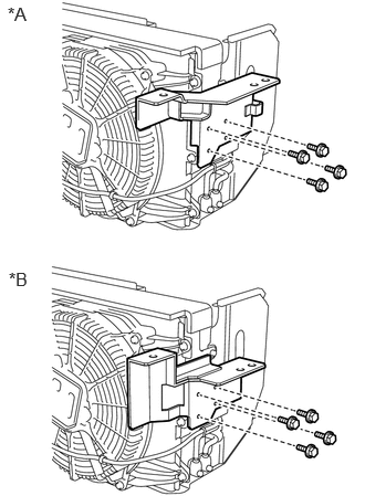
| *A | except Normal Body |
| *B | for Normal Body |
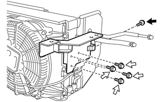
Install the No. 3 cooler condenser bracket with the 4 bolts.
for LHD:
|
|
Bolt (A) |
|
|
Bolt (B) |
Install the No. 3 cooler condenser bracket with the 4 bolts (B).
Install the bolt (A).
Install the 3 No. 1 cooler condenser cushions, 3 No. 2 cooler condenser cushions and 3 No. 1 condenser bracket collars.
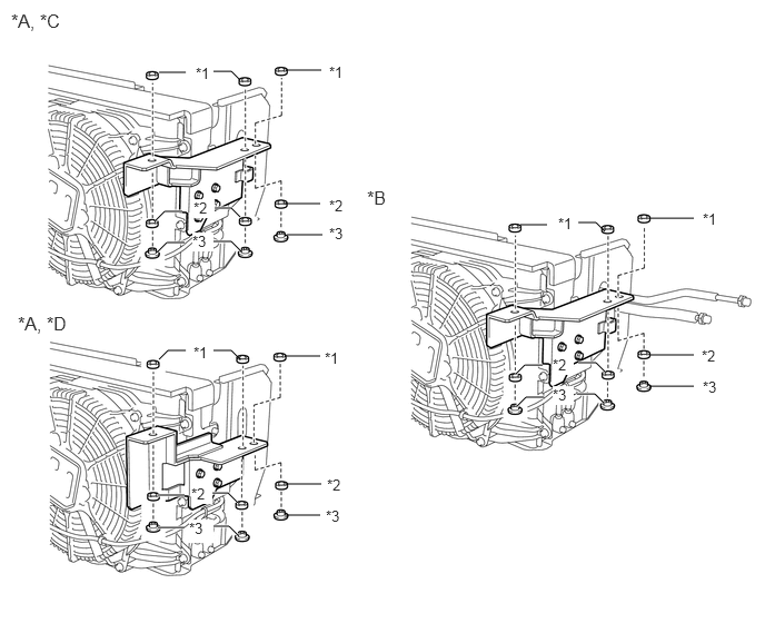
| *A | for RHD | *B | for LHD |
| *C | except Normal Body | *D | for Normal Body |
| *1 | No. 1 Cooler Condenser Cushion | *2 | No. 2 Cooler Condenser Cushion |
| *3 | No. 1 Condenser Bracket Collar | - | - |