N04C-VJ ENGINE CONTROL ECD SYSTEM P0045 Turbocharger / Supercharger Boost Control Solenoid Circuit / Open
DESCRIPTION
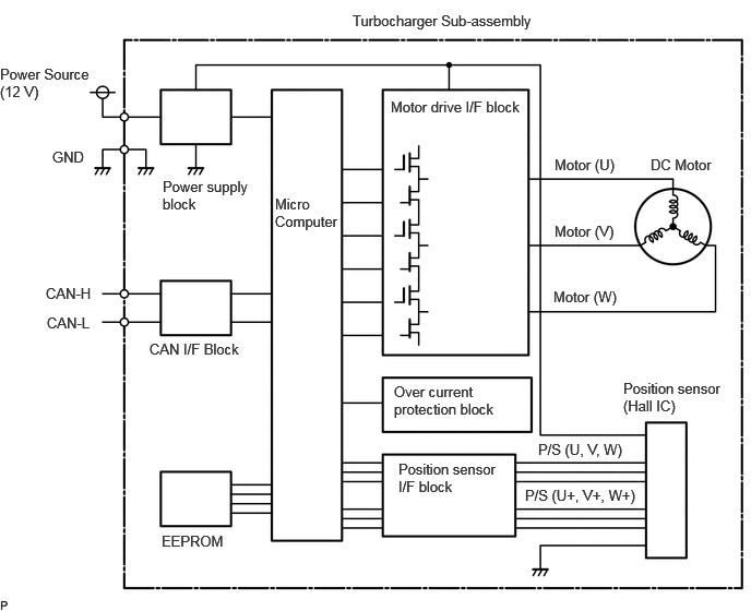
The VNT actuator moves the nozzle vane steplessly by the LEA (Linear Electric Actuator) to control the turbo speed and boost pressure.
The LEA has a sensor to detect the movement of the actuator, always monitoring the target and actual value of the nozzle vane opening.
Wiping operation is performed while the engine is stopped for the purpose of removing soot and oil coming out from the range of vane operation and checking the turbo mechanical operating range for abnormality.
| DTC No. | Detection Item | DTC Detection Condition | Trouble Area | MIL | Memory |
|---|---|---|---|---|---|
| P0045 | Turbocharger / Supercharger Boost Control Solenoid Circuit / Open | Ignition switch ON, battery voltage 11 to 14 V, and engine stopped or 5 seconds or more elapse with engine speed at 500 rpm or more
(1 trip detection logic) ·
Follow-up failure detected due to abnormal movement or the variable nozzle operation link being stuck ·
Abnormally high temperature detected in turbocharger sub-assembly (variable nozzle controller) ·
Open or short in the internal motor or position sensor of the turbocharger sub-assembly (variable nozzle controller) ·
The stopper position of the variable nozzle operation link has deviated and an operating range malfunction is detected |
·
The stopper position of the variable nozzle operation link has deviated and an operating range malfunction is detected ·
Foreign matter jammed in the variable nozzle operation link or stop position deviated ·
Temperature increase around turbocharger sub-assembly (variable nozzle controller) |
Comes on | DTC stored |
CONFIRMATION DRIVING PATTERN
| DTC No. | DTC Detection Drive Pattern |
|---|---|
| P0045 | ·
Idle the engine for 5 seconds after warming up the engine ·
Ignition switch ON to off (wiping operation) |
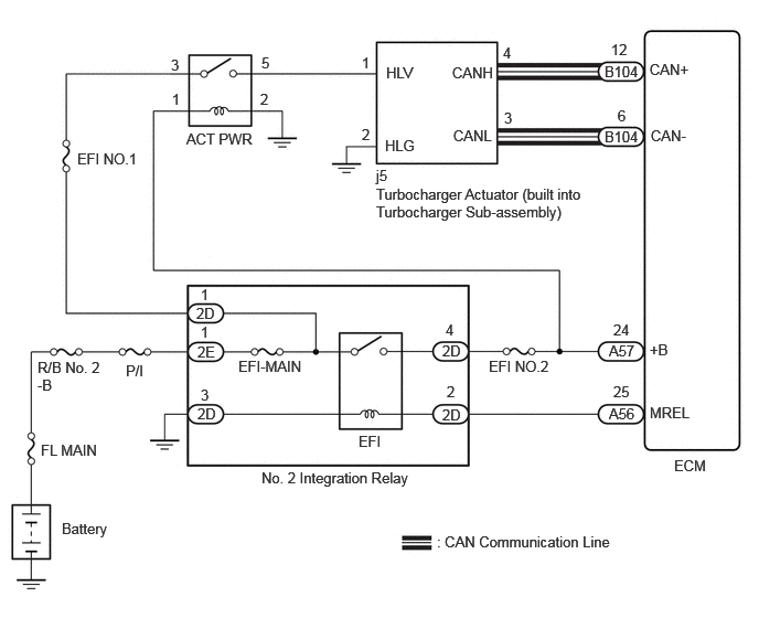
WIRING DIAGRAM
CAUTION / NOTICE / HINT
- NOTICE:
- ·
After replacing the ECM, the new ECM needs registration (Click here Engine / Hybrid System>N04C-VJ (ENGINE CONTROL)>ECD SYSTEM>REGISTRATION) and initialization (Click here Engine / Hybrid System>N04C-VJ (ENGINE CONTROL)>ECD SYSTEM>INITIALIZATION).
·Inspect the fuses for circuits related to this system before performing the following inspection procedure.
- HINT:
-
Read freeze frame data using the GTS. Freeze frame data records the engine condition when malfunctions are detected. When troubleshooting, freeze frame data can help determine if the vehicle was moving or stationary, if the engine was warmed up or not, and other data from the time the malfunction occurred.
PROCEDURE
Connect the GTS to the DLC3.
Turn the ignition switch to ON.
Turn the GTS on.
Enter the following menus: Powertrain / Engine / Trouble Codes.
Read the DTCs.
- Result:
Result Proceed to DTC P0045 and other DTCs are output A DTC P0045 is output B
A
B
Diagnose relevant DTCs.
Click hereEngine / Hybrid System>N04C-VJ (ENGINE CONTROL)>ECD SYSTEM>DIAGNOSTIC TROUBLE CODE CHART
Repair any malfunctioning parts indicated by related DTCs.
- Result:
Proceed to NEXT
NEXT
Connect the GTS to the DLC3.
Turn the ignition switch to ON and turn the GTS on.
Clear the DTCs.
Turn the ignition switch off for 30 seconds or more.
- HINT:
-
Ignition switch ON to off verifies the wiping operation of the VNT actuator (DC motor).
Perform the confirmation driving pattern.
Turn the GTS on.
Enter the following menus: Powertrain / Engine / Trouble Codes.
Read Current DTCs.
- Result:
Result Proceed to DTC P0045 is not output A DTC P0045 is output B
A
B
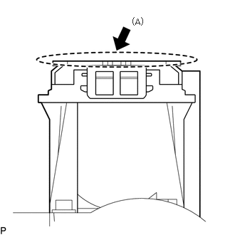
Check that there are no possible causes for a temperature increase around the turbocharger sub-assembly (variable nozzle controller).
- Standard:
There are no holes in the insulator, cracks, or exhaust gas leaks that could lead to an increase in temperature
- HINT:
-
If the temperature of the variable nozzle controller upper surface (A) rises, P0045 is output.
- Result:
Proceed to OK NG
OK
NG
Check that no foreign matter is stuck around the turbocharger sub-assembly (variable nozzle controller) variable nozzle operation link.
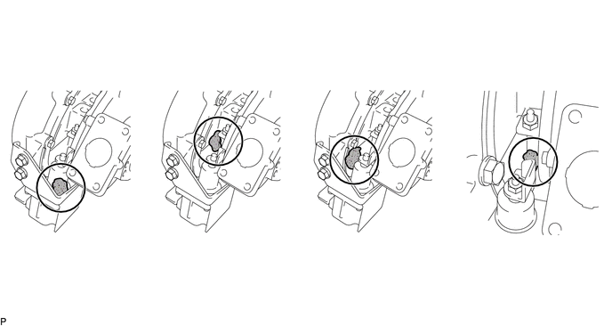
- Result:
Result Proceed to Foreign matter stuck around the variable nozzle operation link
(proceed to the next procedure after removing the foreign objects)A No foreign matter stuck around the variable nozzle operation link B
A
B
Connect the GTS to the DLC3.
Turn the ignition switch to ON and turn the GTS on.
Enter the following menus: Powertrain / Engine / Active Test / Control the VN Turbo Position / Data List / Target VN Turbo Position and Actual VN Turbo Position.
Check each step from 90 to 0% of the time lag of the target VN turbo position and actual VN turbo position.
- NOTICE:
-
Perform the inspection while the engine is stopped to avoid engine damages.
- Standard:
The response delay should be less than 3 seconds.
- Result:
Proceed to OK NG
OK
NG
Check the past repair history to check whether previously output turbocharger sub-assembly DTCs were cleared.
- HINT:
-
There are cases where previously stored P0045 DTCs were not cleared during repair work. However, if the MIL illuminates after repair, the engine output drops, or black smoke is emitted after repair, this is not the result of DTCs not being cleared. Therefore, replace the turbocharger sub-assembly (variable nozzle controller).
- Standard:
No entries for turbocharger sub-assembly DTCs in the past repair history.
Or, the MIL illuminates, there is insufficient power, or there is no black smoke emitted after repair
- Result:
Proceed to OK NG
OK
NG
Check that no foreign matter is stuck around the turbocharger sub-assembly (variable nozzle controller) variable nozzle operation link.
- Result:
Result Proceed to Foreign matter stuck around the variable nozzle operation link
(proceed to the next procedure after removing the foreign objects)A No foreign matter stuck around the variable nozzle operation link B
A
B
Connect the GTS to the DLC3.
Turn the ignition switch to ON and turn the GTS on.
Clear the DTCs.
Turn the ignition switch off for 5 seconds or more.
- HINT:
-
Variable vane performs wiping movement.
Perform the confirmation driving pattern.
Turn the GTS on.
Enter the following menus: Powertrain / Engine / Trouble Codes.
Read Current DTCs.
- Result:
Result Proceed to DTCs are not output* A DTC P0045 is output B
- HINT:
-
*: P0045 is output due to foreign matter jammed in the variable nozzle operation link.
A
B
Connect the GTS to the DLC3.
Turn the ignition switch to ON and turn the GTS on.
Enter the following menus: Powertrain / Engine / Active Test / Control the VN Turbo Position / Data List / Target VN Turbo Position and Actual VN Turbo Position.
Check each step from 90 to 0% of the time lag of the target VN turbo position and actual VN turbo position.
- NOTICE:
-
Perform the inspection while the engine is stopped to avoid engine damages.
- Standard:
The response delay should be less than 3 seconds.
- Result:
Proceed to OK NG
OK
NG