N04C-VJ FUEL FUEL SUPPLY PUMP REMOVAL
PROCEDURE

 1.DISCONNECT CABLE FROM NEGATIVE BATTERY TERMINAL
53712C
2.REMOVE FRONT FENDER APRON LH
3.DISCHARGE FUEL
25608
4.REMOVE EGR COOLER SUB-ASSEMBLY
11202D
5.REMOVE NO. 2 CYLINDER HEAD COVER SUB-ASSEMBLY
6.SET NO. 1 CYLINDER TO TDC/COMPRESSION
17113
7.REMOVE INTAKE PIPE
58396E
8.REMOVE WIRE HARNESS CLAMP BRACKET
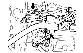
Disconnect the 3 clamps.
Remove the 2 bolts and disconnect the ground wire and wire harness.
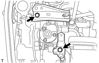
Remove the 2 bolts and 2 wire harness clamp brackets.
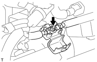
Remove the nut and disconnect the engine wire.
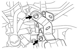
Remove the 2 bolts and wire harness clamp bracket.
9.REMOVE FUEL PIPE
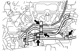
| *1 | Fuel Filter To Injection Pump Fuel Pipe |
Remove the 3 nuts and 3 fuel pipe clamps.
Remove the bolt and disconnect the fuel filter to injection pump fuel pipe.
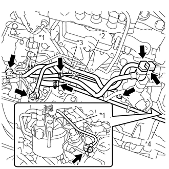
| *1 | Fuel Filter To Injection Pump Fuel Pipe Sub-assembly |
| *2 | No. 1 Fuel Pipe |
| *3 | No. 2 Fuel Pipe |
| *4 | Fuel Filter To Injection Pump Fuel Pipe |
Remove the 6 union bolts, No. 1 fuel pipe, No. 2 fuel pipe, fuel filter to injection pump fuel pipe sub-assembly and gaskets.
Slide the 2 hose clamps and disconnect the 2 fuel tubes from the No. 2 fuel pipe and fuel filter to injection pump fuel pipe.
23802E
10.REMOVE FUEL PIPE SUB-ASSEMBLY
Remove the 2 nuts and fuel pipe clamps.
Using a 17 mm union nut wrench, loosen the 2 union nuts.
Remove the fuel pipe sub-assembly.
- NOTICE:
-
Be sure to prevent foreign matter or water from entering the lines.
11.REMOVE CRANKSHAFT POSITION SENSOR
22100
12.REMOVE SUPPLY PUMP ASSEMBLY
Disconnect the 2 connectors.
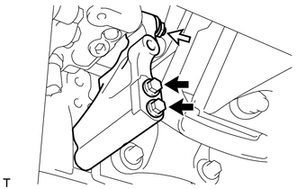

|
Bolt |

|
Nut |
Remove the nut, spacer, 2 bolts and injection pump stay.
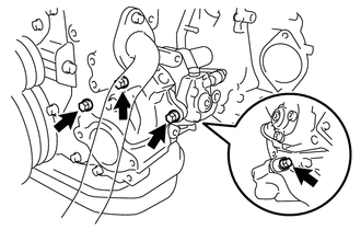
Remove the 4 bolts and supply pump assembly.
Remove the O-ring from the timer cover.
13613
13.REMOVE INJECTION PUMP DRIVE GEAR
Mount the injection pump drive gear in a vise between aluminum plates.
Loosen the nuts, and then lightly tap on the ends of the nuts with a plastic-faced hammer to detach the injection pump drive gear from the supply pump assembly.
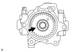
Remove the nut, injection pump drive gear and crankshaft angle sensor plate.
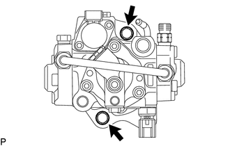
Remove the 2 bolts and timer cover.
Remove the O-ring from the timer cover.