AIR CONDITIONING COMPRESSOR(for 1HZ) INSTALLATION
CAUTION / NOTICE / HINT
- HINT:
- ·
Use the same procedure for RHD and LHD vehicles.
·The procedure listed below is for LHD vehicles.
PROCEDURE

 1.ADJUST COMPRESSOR OIL
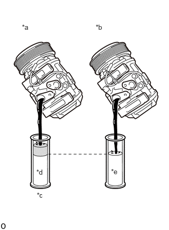
| *a | New Cooler Compressor Assembly |
| *b | Removed Cooler Compressor Assembly |
| *c | Drain Extra Oil (A - B) |
| *d | A |
| *e | B |
WhWhen replacing the cooler compressor assembly with a new one, gradually discharge the refrigerant gas from the service valve. Then drain the following amount of oil from the new compressor before installation, so that the amount of oil contained in it is the same as that in the cooler compressor assembly to be replaced.
- HINT:
-
New cooler compressors assembly are filled with sufficient oil for the whole cycle. Therefore, it is necessary to drain excess oil from the condenser and cooling unit.
- Standard:
(The amount of oil inside a new cooler compressor assembly: 400 (+/- 30) cc (13.5 (+/- 1.01) fl.oz.)) - (The amount of oil in the removed cooler compressor assembly) = The amount of oil to be removed from the new cooler compressor assembly
- NOTICE:
- ·
When checking the compressor oil level, observe the precautions for cooler removal/installation.
·If a new cooler compressor assembly is installed without removing the excess oil, the amount of oil in the system becomes too large. This prevents heat exchange in the refrigerant cycle and causes refrigeration failure.
·If the amount of oil in the removed cooler compressor assembly is too small, check for oil leakage.
·Use ND-OIL8 compressor oil.
88431
2.INSTALL NO. 1 COMPRESSOR MOUNTING BRACKET
Install the No. 1 compressor mounting bracket with the 5 bolts.
- Torque:
- 46.6 N*m (475 kgf*cm, 34 ft.*lbf)
88444
3.INSTALL IDLE PULLEY BRACKET
Install the idle pulley bracket with the 3 bolts.
- Torque:
- 36.8 N*m (375 kgf*cm, 27 ft.*lbf)
4.INSTALL COMPRESSOR WITH MAGNETIC CLUTCH
Install the compressor together with hose with the 4 bolts.
- Torque:
46.6 N*m (475 kgf*cm, 34 ft.*lbf)
- NOTICE:
-
Do not apply excessive force to the air conditioning hose.
88711
5.CONNECT NO. 1 COOLER REFRIGERANT DISCHARGE HOSE
Remove the vinyl tape from the No. 1 cooler refrigerant discharge hose and connecting part of the compressor with magnet clutch and then sufficiently apply compressor oil to a new O-ring and the fitting surface of the No. 1 cooler refrigerant discharge hose.
- Compressor Oil:
ND-OIL 8 or equivalent
Install the O-ring to the No. 1 cooler refrigerant discharge hose.
- NOTICE:
-
Keep the O-ring and O-ring fitting surface free of foreign matter.
Install the No. 1 cooler refrigerant discharge hose to the compressor with magnet clutch with the bolt.
- Torque:
- 9.8 N*m (100 kgf*cm, 87 in.*lbf)
- NOTICE:
-
Make sure not to cut the O-ring while installing it. (Cut O-rings cannot be installed.)
88712
6.CONNECT NO. 1 COOLER REFRIGERANT SUCTION HOSE
Remove the vinyl tape from the No. 1 cooler refrigerant suction hose and connecting part of the compressor with magnet clutch and then sufficiently apply compressor oil to a new O-ring and the fitting surface of the No. 1 cooler refrigerant suction hose.
Install the O-ring to the No. 1 cooler refrigerant suction hose.
- NOTICE:
-
Keep the O-ring and O-ring fitting surface free of foreign matter.
Connect the No. 1 cooler refrigerant suction hose to the compressor with magnet clutch with the nut.
- Torque:
- 9.8 N*m (100 kgf*cm, 87 in.*lbf)
- NOTICE:
-
Make sure not to cut the O-ring while installing it. (Cut O-rings cannot be installed.)
Connect the connector.
88310A
7.INSTALL NO. 1 V (COOLER COMPRESSOR TO CRANKSHAFT PULLEY) BELT
58701A
8.INSTALL FRONT ENGINE SERVICE COVER PANEL SUB-ASSEMBLY
33506F
9.INSTALL FLOOR SHIFT CONTROL SHIFT LEVER RETAINER SUB-ASSEMBLY
58123A
10.INSTALL SHIFT AND SELECT LEVER SUPPORT WITH BOOTS
11. CHARGE REFRIGERANT
12. WARM UP ENGINE
13.INSPECT FOR REFRIGERANT LEAK
58420
14.INSTALL NO. 2 ENGINE SERVICE HOLE COVER ASSEMBLY
58521D
15.INSTALL ENGINE SERVICE HOLE COVER MAT
58734B
16.INSTALL REAR ENGINE SERVICE COVER WEATHERSTRIP
58410
17.INSTALL ENGINE SERVICE HOLE COVER