RM24M0E
_51
Engine / Hybrid System
_059545
2AZ-FE EMISSION CONTROL
_0291816
AIR FUEL RATIO SENSOR
A
2AZ-FE EMISSION CONTROL AIR FUEL RATIO SENSOR INSTALLATION
PROCEDURE

 89467B
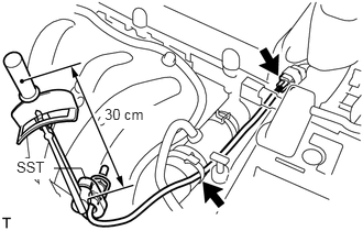
1.INSTALL AIR FUEL RATIO SENSOR (for Bank 1 Sensor 1)
a.
0.813,1.698 0.771,1.594
0.771,1.594 0.51,1.594
false
0.99,1 1.49,1.219
0.5,0.219
10
true
30 cm
0.156,1.5 0.469,1.698
0.313,0.198
10
true
SST
Using SST, install the sensor to the exhaust manifold.
- SST
- 09224-00010
- Torque:
- 40 N*m (408 kgf*cm, 30 ft.*lbf)
for use with SST
- 44 N*m (449 kgf*cm, 32 ft.*lbf)
for use without SST
- HINT:
- ·
Use a torque wrench with a fulcrum length of 30 cm (11.81 in.).
·Make sure SST and wrench are connected in a straight line.
b.
Connect the sensor connector.
17167
2.INSTALL NO. 1 EXHAUST MANIFOLD HEAT INSULATOR
a.
Install the insulator with the 4 bolts.
- Torque:
- 12 N*m (122 kgf*cm, 9 ft.*lbf)
28800
3.CONNECT CABLE TO NEGATIVE BATTERY TERMINAL
4.PERFORM INITIALIZATION
a.
Perform initialization (see page General>INTRODUCTION>REPAIR INSTRUCTION>INITIALIZATION).
- NOTICE:
-
Certain systems need to be initialized after disconnecting and reconnecting the cable from the negative (-) battery terminal.
5.CHECK FOR EXHAUST GAS LEAKS