2GR-FE ENGINE MECHANICAL DRIVE BELT INSTALLATION
PROCEDURE

 16361A
1.INSTALL V-RIBBED BELT
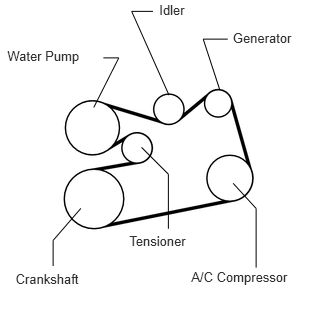
Install the V-ribbed belt.
If it is difficult to install the V-ribbed belt, perform the following procedure:
Put the V-ribbed belt on every pulley except the tensioner pulley as shown in the illustration.
While releasing the belt tension by turning the belt tensioner counterclockwise, put the V-ribbed belt on the tensioner pulley.
- NOTICE:
- ·
Put the backside of the V-ribbed belt on the tensioner pulley and idler pulley.
·Check that the V-ribbed belt is properly set to each pulley.
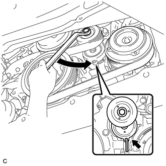
Turn the belt tensioner counterclockwise and remove the bar.
After installing the V-ribbed belt, check that it fits properly in the ribbed grooves. Confirm that the belt has not slipped out of the grooves on the bottom of the crank pulley by hand.
11209
2.INSTALL V-BANK COVER ASSEMBLY
53736
3.INSTALL FRONT FENDER APRON SEAL RH
4.INSTALL FRONT WHEEL RH
T = 103 N*m{ 1,050 kgf*cm 76 ft.*lbf }