2GR-FE ENGINE MECHANICAL ENGINE UNIT REASSEMBLY
CAUTION / NOTICE / HINT
- HINT:
- ·
Select the No. 1 valve rocker arm sub-assemblies, inner compression springs and valve spring retainers based on the identification mark on the cylinder head.
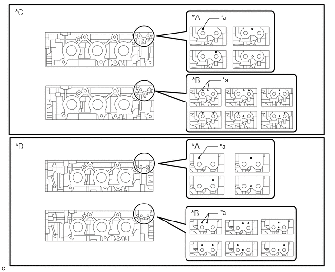 4.344,0.594 4.479,0.396 4.479,0.396 4.688,0.396 false 4.333,1.906 4.479,1.719 4.479,1.719 4.719,1.719 false 4.448,1.917 4.479,1.729 false 4.26,3.365 4.438,3.146 4.438,3.146 4.656,3.146 false 4.323,4.76 4.469,4.573 4.469,4.573 4.656,4.573 false 4.438,4.76 4.469,4.573 false 4.104,0.271 4.615,0.677 0.51,0.406 12 false *A 4.104,1.615 4.615,2.021 0.51,0.406 12 false *B 4.094,3.031 4.604,3.438 0.51,0.406 12 false *A 4.083,4.469 4.594,4.875 0.51,0.406 12 false *B 0.313,0.156 0.823,0.563 0.51,0.406 12 false *C 0.323,3.031 0.833,3.438 0.51,0.406 12 false *D 4.719,0.292 5.229,0.698 0.51,0.406 10 false *a 4.76,1.625 5.271,2.031 0.51,0.406 10 false *a 4.698,3.052 5.208,3.458 0.51,0.406 10 false *a 4.708,4.469 5.219,4.875 0.51,0.406 10 false *a
Text in Illustration *A Type A *B Type B *C Cylinder Head RH *D Cylinder Head LH *a Identification Mark - -
Type Identification Mark Inner Compression Spring Shape A 1 Hole Straight B 2 Holes Taper
· 0.052,0.063 1.698,4.5 1.646,4.438 1.781,0.063 3.385,4.5 1.604,4.438 1.146,2.094 1.146,2.354 false 2.854,2.083 2.854,2.344 false 2.604,2.979 2.885,2.979 false 0.896,3.01 1.167,3.01 false 0.958,3.802 1.229,3.802 false 2.656,3.885 2.927,3.885 false 0.104,0.083 0.5,0.333 0.396,0.25 12 false *A 1.833,0.083 2.229,0.333 0.396,0.25 12 false *B 1.396,0.885 1.667,1.125 0.271,0.24 10 false *b 3.125,0.875 3.344,1.115 0.219,0.24 10 false *b 1.042,2.354 1.313,2.594 0.271,0.24 10 false *1 2.771,2.354 3.042,2.594 0.271,0.24 10 false *1 0.615,2.458 0.885,2.698 0.271,0.24 10 false *a 2.344,2.479 2.615,2.719 0.271,0.24 10 false *a 2.917,2.896 3.188,3.135 0.271,0.24 10 false *2 1.229,2.917 1.5,3.156 0.271,0.24 10 false *2 1.281,3.708 1.552,3.948 0.271,0.24 10 false *3 2.99,3.781 3.26,4.021 0.271,0.24 10 false *3
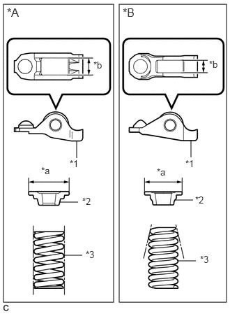
There are 2 types of No. 1 valve rocker arm sub-assemblies, inner compression springs and valve spring retainers. The 2 types are not interchangeable.
Text in Illustration *A Type A *B Type B *1 No. 1 Valve Rocker Arm Sub-assembly *2 Valve Spring Retainer *3 Inner Compression Spring *a Valve Spring Retainer Diameter *b No. 1 Valve Rocker Arm Sub-assembly Roller Width
Type No. 1 Valve Rocker Arm Sub-assembly Roller Width Valve Spring Retainer Diameter Inner Compression Spring Shape A 10.7 mm (0.421 in.) 23.4 mm (0.921 in.) Straight B 8.0 mm (0.315 in.) 18.9 mm (0.744 in.) Taper
PROCEDURE

 1.INSTALL STRAIGHT PIN
Using a plastic hammer, tap in new straight pins to the cylinder block sub-assembly.
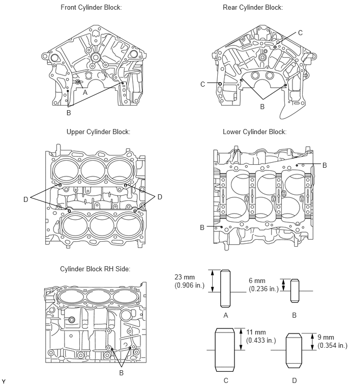
- Standard protrusion:
Item Protrusion Pin A 23 mm (0.906 in.) Pin B 6 mm (0.236 in.) Pin C 11 mm (0.433 in.) Pin D 9 mm (0.354 in.)
2.INSTALL STUD BOLT
Using E8 and E10 "TORX" socket wrenches, install the stud bolts.
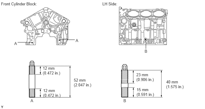
- Torque:
- Bolt (A) : 10 N*m (102 kgf*cm, 7 ft.*lbf)
- Bolt (B) : 17 N*m (173 kgf*cm, 13 ft.*lbf)
15708
3.INSTALL NO. 1 OIL NOZZLE SUB-ASSEMBLY
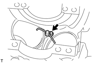
Using a 5 mm hexagon wrench, install the 3 No. 1 oil nozzle sub-assemblies with the 3 bolts.
- Torque:
- 9.0 N*m (92 kgf*cm, 80 in.*lbf)
13101
4.INSTALL PISTON SUB-ASSEMBLY WITH PIN
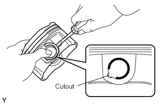
Using a screwdriver, install a new piston pin hole snap ring at one end of the piston pin hole.
- HINT:
-
Be sure that the end gap of the piston pin hole snap ring is not aligned with the cutout of the piston.
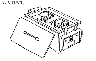
Gradually heat the piston to approximately 80°C (176°F).
Coat the piston pin with engine oil.
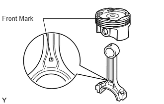
Align the front marks of the piston and connecting rod sub-assembly, and push in the piston pin with your thumb.
- HINT:
-
The piston sub-assembly with pin are a matched set.
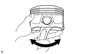
Check the fitting condition between the piston sub-assembly with pin by trying to move the piston back and forth on the piston pin.
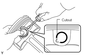
Using a screwdriver, install a new piston pin hole snap ring at the other end of the piston pin hole.
- HINT:
-
Be sure that the end gap of the piston pin hole snap ring is not aligned with the cutout of the piston.
13011
5.INSTALL PISTON RING SET
Install the oil ring expander and 2 side rails by hand.
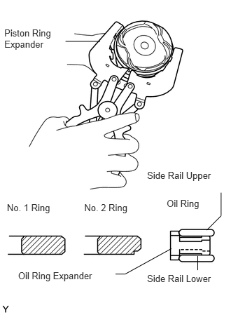
Using a piston ring expander, install the 2 compression rings as shown in the illustration.
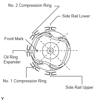
Position the piston rings so that the ring ends are as shown in the illustration.
- NOTICE:
-
Do not align the piston ring ends.
11711
6.INSTALL CRANKSHAFT BEARING
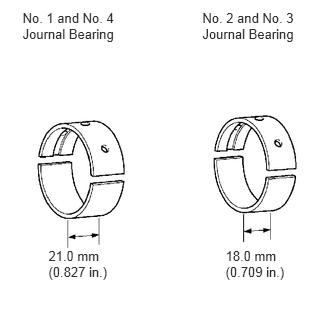
Clean the main journals and both surfaces of the crankshaft bearings.
- NOTICE:
-
Crankshaft bearings come in widths of 18.0 mm (0.709 in.) and 21.0 mm (0.827 in.). Install the 21.0 mm (0.827 in.) bearings in the No. 1 and No. 4 cylinder block journal positions with the crankshaft bearing caps. Install the 18.0 mm (0.709 in.) bearings in the No. 2 and No. 3 positions.
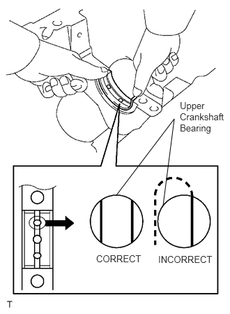
Install the upper crankshaft bearing.
Install the upper crankshaft bearings to the cylinder block sub-assembly as shown in the illustration.
- NOTICE:
- ·
Do not apply engine oil to the upper crankshaft bearings and the contact surfaces.
·Both sides of the oil groove in the cylinder block sub-assembly should be visible through the oil feed holes in the upper crankshaft bearing. The amount visible on each side of the holes should be equal.
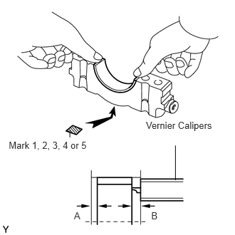
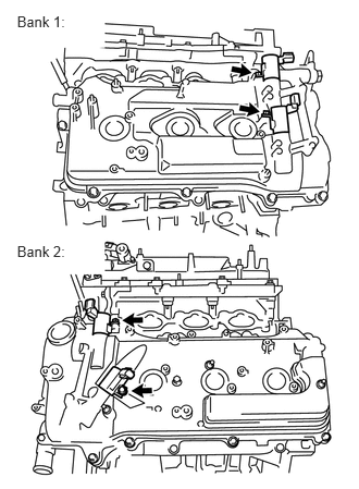
Install the lower crankshaft bearing.
Install the lower crankshaft bearings to the crankshaft bearing caps.
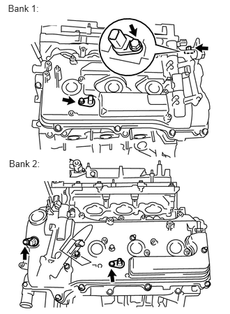
Using vernier calipers, measure the distance between the edges of the crankshaft bearing cap and the lower crankshaft bearing.
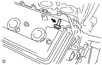
- Dimension (A - B):
0.7 mm (0.0276 in.) or less
- NOTICE:
-
Do not apply engine oil to the lower crankshaft bearings and the contact surfaces.
11011
7.INSTALL UPPER CRANKSHAFT THRUST WASHER
Apply engine oil to the upper crankshaft thrust washers.
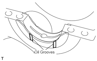
Install the 2 upper crankshaft thrust washers under the No. 2 journal position of the cylinder block sub-assembly with the oil grooves facing outward.
13411
8.INSTALL CRANKSHAFT
Apply engine oil to the upper crankshaft bearings, then place the crankshaft on the cylinder block sub-assembly.
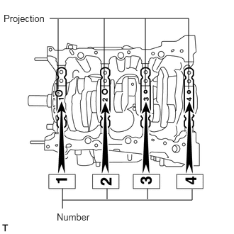
Confirm the projections and numbers of the crankshaft bearing caps and install the crankshaft bearing caps on the cylinder block sub-assembly.
- HINT:
-
A number is marked on each crankshaft bearing cap to indicate the installation position.
Apply a light coat of engine oil to the threads and the bottom of the heads of the crankshaft bearing cap bolts.
Temporarily install the 8 crankshaft bearing cap bolts to the inside positions.
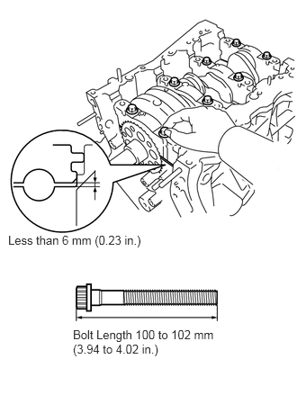
Push the crankshaft bearing cap with your hand until the clearance between the crankshaft bearing cap and the cylinder block sub-assembly is less than 6 mm (0.23 in.) by using the 2 inside crankshaft bearing cap bolts as a guide.
- Bolt length:
100 to 102 mm (3.94 to 4.02 in.)
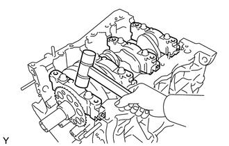
Using a plastic hammer, lightly tap the crankshaft bearing cap to ensure a proper fit.
Apply a light coat of engine oil to the threads and under the heads of the 8 crankshaft bearing cap bolts.
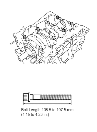
Temporarily install the 8 crankshaft bearing cap bolts to the outside positions.
Install the crankshaft bearing cap bolts.
- HINT:
-
The crankshaft bearing cap bolts are tightened in 2 progressive steps.
Step 1
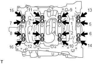
Uniformly tighten the 16 crankshaft bearing cap bolts in the sequence shown in the illustration.
- Torque:
- 61 N*m (622 kgf*cm, 45 ft.*lbf)
If any of the crankshaft bearing cap bolts does not meet the specified torque, replace it.
Step 2
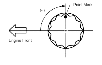
Mark the front of the crankshaft bearing cap bolts with paint.
Tighten the crankshaft bearing cap bolts 90° in the order above.
Check that each paint mark is now at a 90° angle to the front.
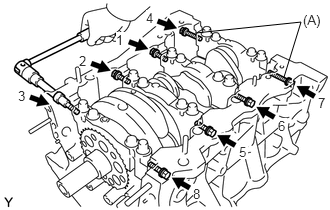
Install 8 new seal washers and uniformly tighten the 8 crankshaft bearing cap bolts in several steps and in the sequence shown in the illustration.
- Torque:
- 52 N*m (525 kgf*cm, 38 ft.*lbf)
- Bolt length:
Item Length Bolt A 45 mm (1.77 in.) Except bolt A 30 mm (1.18 in.)
Check that the crankshaft turns smoothly.
Check the crankshaft thrust clearance (See page Engine / Hybrid System>2GR-FE ENGINE MECHANICAL>ENGINE UNIT>INSPECTION).
13041
9.INSTALL CONNECTING ROD BEARING
Install the connecting rod bearings to the connecting rod sub-assembly and connecting rod cap.
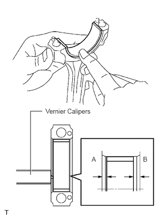
Using vernier calipers, measure the distance between the edges of the connecting rod sub-assembly and crankshaft bearing cap and the edge of the connecting rod bearing.
- Dimension (A - B):
0.7 mm (0.0276 in.) or less
- NOTICE:
-
Do not apply engine oil to the connecting rod bearings and the contact surfaces.
10.INSTALL PISTON SUB-ASSEMBLY WITH CONNECTING ROD
Apply engine oil to the cylinder walls, pistons, and surfaces of the connecting rod bearings.
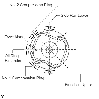
Position the piston rings so that the ring ends are as shown in the illustration.
- NOTICE:
-
Do not align the ring ends.
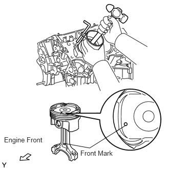
Using a piston ring compressor, push the correctly numbered piston and connecting rod sub-assembly into the cylinder with the front mark of the piston facing forward.
- NOTICE:
-
Match the numbered connecting rod cap with the connecting rod sub-assembly.
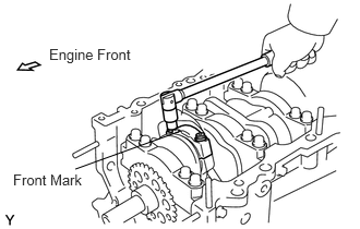
Check that the front mark of the connecting rod cap is facing forward.
Apply a light coat of engine oil to the threads and under the heads of the connecting rod cap bolts.
Install the connecting rod cap bolts.
- HINT:
-
The connecting rod cap bolts are tightened in 2 progressive steps.
Step 1
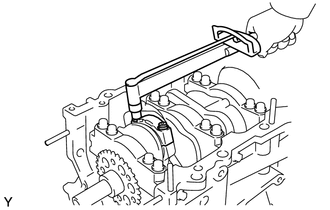
Alternately tighten the connecting rod cap bolts in several steps.
- Torque:
- 25 N*m (255 kgf*cm, 18 ft.*lbf)
Step 2
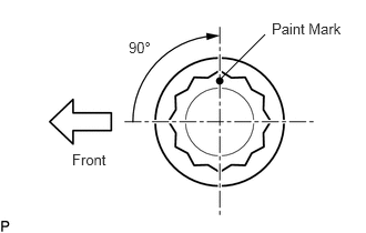
Mark the front of connecting cap bolts with paint.
Tighten the connecting rod cap bolts 90° as shown in the illustration.
Check that each paint mark is now at a 90° angle to the front.
Check that the crankshaft turns smoothly.
Check the connecting rod thrust clearance (See page Engine / Hybrid System>2GR-FE ENGINE MECHANICAL>ENGINE UNIT>INSPECTION).
11122
11.INSTALL INTAKE VALVE GUIDE BUSH
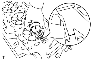
Using a caliper gauge, measure the intake valve guide bush bore diameter of the cylinder head sub-assembly.
- Cylinder Bore Diameter:
10.285 to 10.306 mm (0.4049 to 0.4057 in.)
- Select a new intake valve guide bush (STD or O/S 0.05):
Bush size Bush bore diameter STD 10.285 to 10.306 mm (0.4049 to 0.4057 in.) O/S 0.05 10.335 to 10.356 mm (0.4069 to 0.4077 in.)
If the intake valve guide bush bore diameter of the cylinder head sub-assembly is greater than 10.306 mm (0.4057 in.), machine the intake valve guide bush bore to the dimension of 10.335 to 10.356 mm (0.4069 to 0.4077 in.) to install an O/S 0.05 intake valve guide bush.
If the intake valve guide bush bore diameter of the cylinder head sub-assembly is greater than 10.356 mm (0.4077 in.), replace the cylinder head sub-assembly.
Heat the cylinder head sub-assembly to 80 to 100°C (176 to 212°F).
Place the cylinder head sub-assembly on wooden blocks.
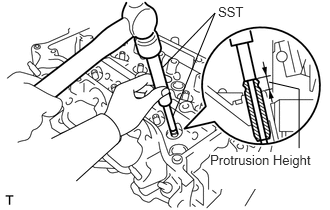
Using SST, tap in new intake valve guide bushes to the specified protrusion height.
- SST
- 09201-10000 (09201-01050)
09950-70010 (09951-07100)
- Protrusion Height:
9.30 to 9.70 mm (0.3661 to 0.3819 in.)
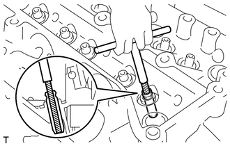
Using a sharp 5.5 mm reamer, ream the intake valve guide bushings to obtain the specified clearance.
- Standard Oil Clearance:
0.025 to 0.060 mm (0.0010 to 0.0023 in.)
11126
12.INSTALL EXHAUST VALVE GUIDE BUSH
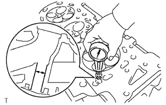
Using a caliper gauge, measure the exhaust valve guide bush bore diameter of the cylinder head sub-assembly.
- Cylinder Bore Diameter:
10.285 to 10.306 mm (0.4049 to 0.4057 in.)
- Select a New Guide Bush (STD or O/S 0.05):
Bush size Bush bore diameter STD 10.285 to 10.306 mm (0.4049 to 0.4057 in.) O/S 0.05 10.335 to 10.356 mm (0.4069 to 0.4077 in.)
If the exhaust valve guide bush bore diameter of the cylinder head sub-assembly is greater than 10.306 mm (0.4057 in.), machine the exhaust valve guide bush bore to the dimension of 10.335 to 10.356 mm (0.4069 to 0.4077 in.) to install an O/S 0.05 exhaust valve guide bush.
If the exhaust valve guide bush bore diameter of the cylinder head sub-assembly is greater than 10.356 mm (0.4077 in.), replace the cylinder head sub-assembly.
Heat the cylinder head sub-assembly to 80 to 100°C (176 to 212°F).
Place the cylinder head sub-assembly on wooden blocks.
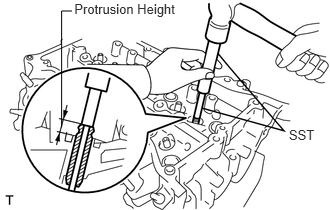
Using SST, tap in new exhaust valve guide bushes to the specified protrusion height.
- SST
- 09201-10000 (09201-01050)
09950-70010 (09951-07100)
- Protrusion Height:
9.30 to 9.70 mm (0.3661 to 0.3819 in.)
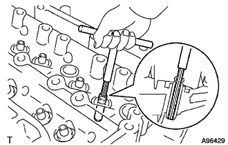
Using a sharp 5.5 mm reamer, ream the exhaust valve guide bushings to obtain the specified clearance.
- Standard Oil Clearance:
0.030 to 0.065 mm (0.0012 to 0.0026 in.)
13.INSTALL RING PIN
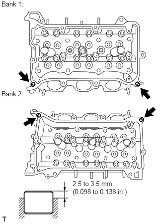
Using a plastic hammer, tap in new 4 ring pins to the specified protrusion height.
- Specified Protrusion Height:
2.5 to 3.5 mm (0.098 to 0.138 in.)
11117E
14.INSTALL NO. 1 STRAIGHT SCREW PLUG
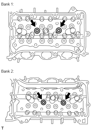
Using a 10 mm hexagon wrench, install 4 new gaskets and the 4 No. 1 straight screw plugs.
- Torque:
- 44 N*m (449 kgf*cm, 32 ft.*lbf)
11117F
15.INSTALL NO. 2 STRAIGHT SCREW PLUG
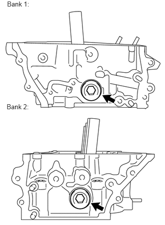
Using a 14 mm hexagon wrench, install 2 new gaskets and the 2 No. 2 straight screw plugs.
- Torque:
- 80 N*m (816 kgf*cm, 59 ft.*lbf)
16.INSTALL STUD BOLT
- NOTICE:
-
If the stud bolt is deformed or the threads are damaged, replace it.
Using E6 and E8 "TORX" socket wrenches, install the stud bolts.
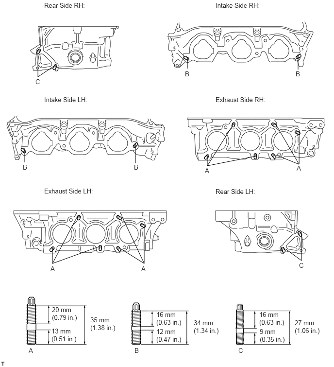
- Torque:
- Bolt (A) and (B) : 10 N*m (102 kgf*cm, 7 ft.*lbf)
- Bolt (C) : 4.0 N*m (41 kgf*cm, 35 in.*lbf)
17.INSTALL STRAIGHT PIN
Using a plastic hammer, tap in new straight pins as shown in the illustration.
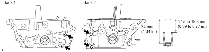
- Protrusion Height:
17.5 to 19.5 mm (0.689 to 0.768 in.)
13734
18.INSTALL VALVE SPRING SEAT
Install the 24 valve spring seats to the cylinder head sub-assembly.
19.INSTALL VALVE STEM OIL SEAL
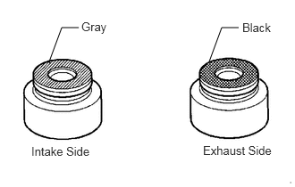
Apply a light coat of engine oil to new valve stem oil seals.
- NOTICE:
-
Pay attention when installing the intake valve stem oil seal and exhaust valve stem oil seal. For example, installing the intake valve stem oil seal to the exhaust side or installing the exhaust valve stem oil seal to the intake side can cause installation problems later.
- HINT:
-
The 12 intake valve stem oil seals are gray and the 12 exhaust valve stem oil seals are black.
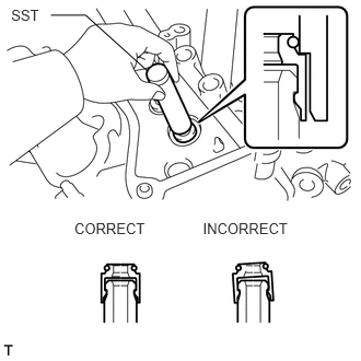
Using SST, push in the 24 valve stem oil seals.
- SST
- 09201-41020
- NOTICE:
-
Failure to use SST will cause the valve stem oil seal to be damaged or improperly seated.
13715
20.INSTALL EXHAUST VALVE
- HINT:
-
0.052,0.063 1.698,4.5 1.646,4.438 1.781,0.063 3.385,4.5 1.604,4.438 1.146,2.094 1.146,2.354 false 2.854,2.083 2.854,2.344 false 2.604,2.979 2.885,2.979 false 0.896,3.01 1.167,3.01 false 0.958,3.802 1.229,3.802 false 2.656,3.885 2.927,3.885 false 0.104,0.083 0.5,0.333 0.396,0.25 12 false *A 1.833,0.083 2.229,0.333 0.396,0.25 12 false *B 1.396,0.885 1.667,1.125 0.271,0.24 10 false *b 3.125,0.875 3.344,1.115 0.219,0.24 10 false *b 1.042,2.354 1.313,2.594 0.271,0.24 10 false *1 2.771,2.354 3.042,2.594 0.271,0.24 10 false *1 0.615,2.458 0.885,2.698 0.271,0.24 10 false *a 2.344,2.479 2.615,2.719 0.271,0.24 10 false *a 2.917,2.896 3.188,3.135 0.271,0.24 10 false *2 1.229,2.917 1.5,3.156 0.271,0.24 10 false *2 1.281,3.708 1.552,3.948 0.271,0.24 10 false *3 2.99,3.781 3.26,4.021 0.271,0.24 10 false *3
-
Type A and Type B can be distinguished by the shape of the inner compression spring.
Text in Illustration *A Type A *B Type B *1 No. 1 Valve Rocker Arm Sub-assembly *2 Valve Spring Retainer *3 Inner Compression Spring *a Valve Spring Retainer Diameter *b No. 1 Valve Rocker Arm Sub-assembly Roller Width
Type No. 1 Valve Rocker Arm Sub-assembly Roller Width Valve Spring Retainer Diameter Inner Compression Spring Shape A 10.7 mm (0.421 in.) 23.4 mm (0.921 in.) Straight B 8.0 mm (0.315 in.) 18.9 mm (0.744 in.) Taper
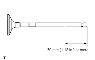
Apply a sufficient coat of engine oil to the tip area of the exhaust valve shown in the illustration.
Type A:
Install the exhaust valve, inner compression spring and valve spring retainer to the cylinder head.
- NOTICE:
-
Install the same parts in the same combination to the original locations.
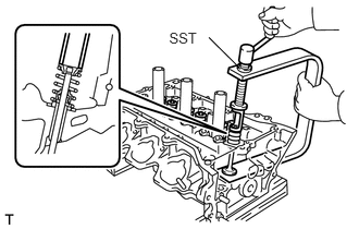
Using SST, compress the inner compression spring and install the 2 valve spring retainer locks.
- SST
- 09202-70020 (09202-00010)
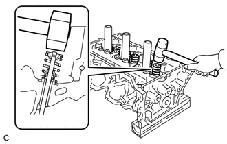
Using a plastic hammer, lightly tap the valve stem tip to ensure a proper fit.
- NOTICE:
-
Be careful not to damage the retainer.
Type B:
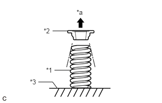
Install the exhaust valve, inner compression spring and valve spring retainer to the cylinder head.
| *1 | Inner Compression Spring |
| *2 | Valve Spring Retainer |
| *3 | Cylinder Head |
| *a | Up |
- NOTICE:
- ·
Install the inner compression spring with its taper side facing upward (towards the valve spring retainer).
·Install the same parts in the same combination to the original locations.
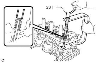
Using SST, compress the inner compression spring and install the 2 valve spring retainer locks.
- SST
- 09202-70020
09202-00020
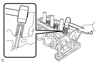
Using a plastic hammer, lightly tap the valve stem tip to ensure a proper fit.
- NOTICE:
-
Be careful not to damage the retainer.
13711
21.INSTALL INTAKE VALVE
- HINT:
-
0.052,0.063 1.698,4.5 1.646,4.438 1.781,0.063 3.385,4.5 1.604,4.438 1.146,2.094 1.146,2.354 false 2.854,2.083 2.854,2.344 false 2.604,2.979 2.885,2.979 false 0.896,3.01 1.167,3.01 false 0.958,3.802 1.229,3.802 false 2.656,3.885 2.927,3.885 false 0.104,0.083 0.5,0.333 0.396,0.25 12 false *A 1.833,0.083 2.229,0.333 0.396,0.25 12 false *B 1.396,0.885 1.667,1.125 0.271,0.24 10 false *b 3.125,0.875 3.344,1.115 0.219,0.24 10 false *b 1.042,2.354 1.313,2.594 0.271,0.24 10 false *1 2.771,2.354 3.042,2.594 0.271,0.24 10 false *1 0.615,2.458 0.885,2.698 0.271,0.24 10 false *a 2.344,2.479 2.615,2.719 0.271,0.24 10 false *a 2.917,2.896 3.188,3.135 0.271,0.24 10 false *2 1.229,2.917 1.5,3.156 0.271,0.24 10 false *2 1.281,3.708 1.552,3.948 0.271,0.24 10 false *3 2.99,3.781 3.26,4.021 0.271,0.24 10 false *3
-
Type A and Type B can be distinguished by the shape of the inner compression spring.
Text in Illustration *A Type A *B Type B *1 No. 1 Valve Rocker Arm Sub-assembly *2 Valve Spring Retainer *3 Inner Compression Spring *a Valve Spring Retainer Diameter *b No. 1 Valve Rocker Arm Sub-assembly Roller Width
Type No. 1 Valve Rocker Arm Sub-assembly Roller Width Valve Spring Retainer Diameter Inner Compression Spring Shape A 10.7 mm (0.421 in.) 23.4 mm (0.921 in.) Straight B 8.0 mm (0.315 in.) 18.9 mm (0.744 in.) Taper
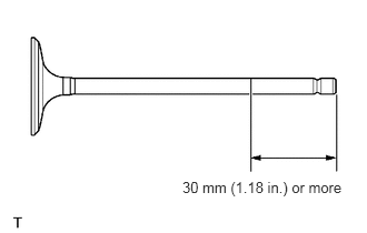
Apply a sufficient coat of engine oil to the tip area of the intake valve shown in the illustration.
Type A:
Install the intake valve, inner compression spring and valve spring retainer to the cylinder head.
- NOTICE:
-
Install the same parts in the same combination to the original locations.
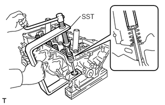
Using SST, compress the inner compression spring and install the 2 valve spring retainer locks.
- SST
- 09202-70020 (09202-00010)
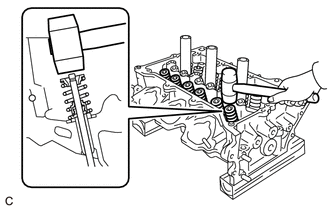
Using a plastic hammer, lightly tap the valve stem tip to ensure a proper fit.
- NOTICE:
-
Be careful not to damage the retainer.
Type B:
Install the intake valve, inner compression spring and valve spring retainer to the cylinder head.
| *1 | Inner Compression Spring |
| *2 | Valve Spring Retainer |
| *3 | Cylinder Head |
| *a | Up |
- NOTICE:
- ·
Install the inner compression spring with its taper side facing upward (towards the valve spring retainer).
·Install the same parts in the same combination to the original locations.
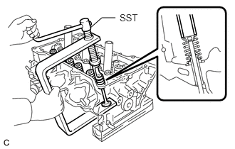
Using SST, compress the inner compression spring and install the 2 valve spring retainer locks.
- SST
- 09202-70020
09202-00020
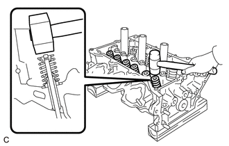
Using a plastic hammer, lightly tap the valve stem tip to ensure a proper fit.
- NOTICE:
-
Be careful not to damage the retainer.
13716
22.INSTALL VALVE STEM CAP
Apply a light coat of engine oil to the 24 valve stem caps.
Install the 24 valve stem caps on the valves.
11381A
23.INSTALL ENGINE REAR OIL SEAL
Place the engine rear oil seal retainer on wooden blocks.
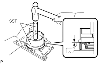
Using SST, tap in a new engine rear oil seal until its surface is flush with the engine rear oil seal retainer edge.
- SST
- 09223-15030
09950-70010 (09951-07100)
- NOTICE:
- ·
Keep the lip free of foreign matter.
·Do not tap in the engine rear oil seal at an angle.
11381
24.INSTALL ENGINE REAR OIL SEAL RETAINER
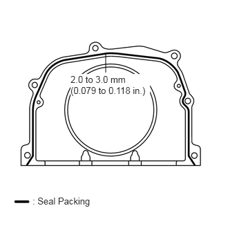
Apply seal packing in a continuous line as shown in the illustration.
- Seal Packing:
Toyota Genuine Seal Packing Black, Three Bond 1207B or equivalent
- Seal Diameter:
2.0 to 3.0 mm (0.079 to 0.118 in.)
- NOTICE:
- ·
Remove any oil from the contact surface.
·Install the engine rear oil seal retainer within 3 minutes after applying seal packing.
·Do not start the engine for at least 2 hours after installation.
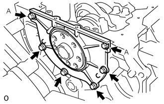
Install the engine rear oil seal retainer with the 6 bolts.
- Torque:
- 10 N*m (102 kgf*cm, 7 ft.*lbf)
- NOTICE:
-
Be sure to apply adhesive 1324 to the bolts (A) before installing them.
- Adhesive:
Toyota Genuine Adhesive 1324, Three Bond 1324 or equivalent
16322
25.INSTALL WATER INLET PIPE
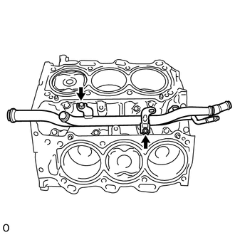
Install the water inlet pipe with the 2 bolts.
- Torque:
- 10 N*m (102 kgf*cm, 7 ft.*lbf)
Connect the No. 1 water by-pass hose and slide the clip to secure it.
11101
26.INSTALL CYLINDER HEAD SUB-ASSEMBLY RH
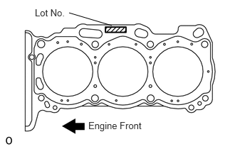
Place the cylinder head gasket on the cylinder block sub-assembly RH with the Lot No. stamp facing upward.
- NOTICE:
- ·
Be careful of the installation direction.
·Gently place the cylinder head sub-assembly RH in order not to damage the cylinder head gasket with the bottom part of the cylinder head sub-assembly.
Place the cylinder head sub-assembly RH on the cylinder block sub-assembly.
- NOTICE:
-
Be careful not to allow any oil to adhere to the bottom part of the cylinder head sub-assembly.
- HINT:
-
The cylinder head bolts are tightened in 3 progressive steps.
Apply a light coat of engine oil to the threads and under the heads of the cylinder head bolts.
Step 1
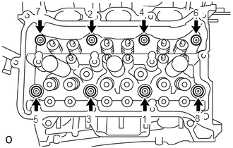
Using a 10 mm bi-hexagon wrench, install and uniformly tighten the 8 cylinder head bolts with the plate washers in several steps and in the sequence shown in the illustration.
- Torque:
- 36 N*m (367 kgf*cm, 27 ft.*lbf)
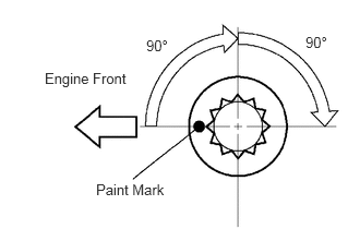
Step 2
Mark the cylinder head bolts with paint as shown in the illustration.
Tighten the cylinder head bolts 90°.
Step 3
Tighten the cylinder head bolts an additional 90°.
Check that the paint mark is now facing rearward.
11102
27.INSTALL CYLINDER HEAD SUB-ASSEMBLY LH
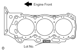
Place the No. 2 cylinder head gasket on the cylinder block sub-assembly LH with the Lot No. stamp facing upward.
- NOTICE:
- ·
Be careful of the installation direction.
·Gently place the cylinder head sub-assembly in order not to damage the cylinder head gasket with the bottom part of the cylinder head sub-assembly.
Place the cylinder head sub-assembly LH on the cylinder block sub-assembly.
- NOTICE:
-
Be careful not to allow any oil to adhere to the bottom part of the cylinder head sub-assembly.
- HINT:
-
The cylinder head bolts are tightened in 3 progressive steps.
Apply a light coat of engine oil to the threads and under the heads of the cylinder head bolts.
Step 1
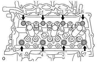
Using a 10 mm bi-hexagon wrench, install and uniformly tighten the 8 cylinder head bolts with the plate washers in several steps in the sequence shown in the illustration.
- Torque:
- 36 N*m (367 kgf*cm, 27 ft.*lbf)
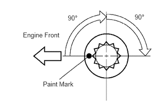
Step 2
Mark the cylinder head bolts with paint as shown in the illustration.
Tighten the cylinder head bolts 90°.
Step 3
Tighten the cylinder head bolts an additional 90°.
Check that the paint mark is now facing rearward.
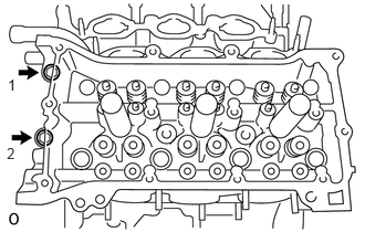
Tighten the 2 bolts in the order shown in the illustration.
- Torque:
- 30 N*m (306 kgf*cm, 22 ft.*lbf)
13750
28.INSTALL VALVE LASH ADJUSTER ASSEMBLY
- NOTICE:
- ·
Keep the valve lash adjuster assembly free of dirt and foreign matter.
·Only use clean engine oil.
Place the 24 valve lash adjuster assemblies into a container filled with engine oil.
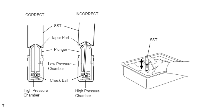
Insert SST's tip into the valve lash adjuster assembly plunger and use the tip to press down on the check ball inside the plunger.
- SST
- 09276-75010
Squeeze SST and valve lash adjuster assembly together to move the plunger up and down 5 to 6 times.
Check the movement of the plunger and bleed the air.
- OK:
Plunger moves up and down.
- NOTICE:
-
When bleeding air from the high-pressure chamber, make sure that the tip of SST is actually pressing the check ball as shown in the illustration. If the check ball is not pressed, air will not bleed.
After bleeding the air, remove SST. Then, try to press the plunger quickly and firmly with a finger.
- OK:
Plunger is very difficult to move.
If the result is not as specified, replace the valve lash adjuster assembly.
Install the 24 valve lash adjuster assemblies.
- NOTICE:
-
Install the valve lash adjuster assembly to the same place where it was removed from.
13801
29.INSTALL NO. 1 VALVE ROCKER ARM SUB-ASSEMBLY
- HINT:
-
0.052,0.063 1.698,4.5 1.646,4.438 1.781,0.063 3.385,4.5 1.604,4.438 1.146,2.094 1.146,2.354 false 2.854,2.083 2.854,2.344 false 2.604,2.979 2.885,2.979 false 0.896,3.01 1.167,3.01 false 0.958,3.802 1.229,3.802 false 2.656,3.885 2.927,3.885 false 0.104,0.083 0.5,0.333 0.396,0.25 12 false *A 1.833,0.083 2.229,0.333 0.396,0.25 12 false *B 1.396,0.885 1.667,1.125 0.271,0.24 10 false *b 3.125,0.875 3.344,1.115 0.219,0.24 10 false *b 1.042,2.354 1.313,2.594 0.271,0.24 10 false *1 2.771,2.354 3.042,2.594 0.271,0.24 10 false *1 0.615,2.458 0.885,2.698 0.271,0.24 10 false *a 2.344,2.479 2.615,2.719 0.271,0.24 10 false *a 2.917,2.896 3.188,3.135 0.271,0.24 10 false *2 1.229,2.917 1.5,3.156 0.271,0.24 10 false *2 1.281,3.708 1.552,3.948 0.271,0.24 10 false *3 2.99,3.781 3.26,4.021 0.271,0.24 10 false *3
-
Type A and Type B can be distinguished by the shape of the compression spring.
Text in Illustration *A Type A *B Type B *1 No. 1 Valve Rocker Arm Sub-assembly *2 Valve Spring Retainer *3 Inner Compression Spring *a Valve Spring Retainer Diameter *b No. 1 Valve Rocker Arm Sub-assembly Roller Width
Type No. 1 Valve Rocker Arm Sub-assembly Roller Width Valve Spring Retainer Diameter Inner Compression Spring Shape A 10.7 mm (0.421 in.) 23.4 mm (0.921 in.) Straight B 8.0 mm (0.315 in.) 18.9 mm (0.744 in.) Taper
Apply engine oil to the valve lash adjuster assembly tip and valve stem cap end.
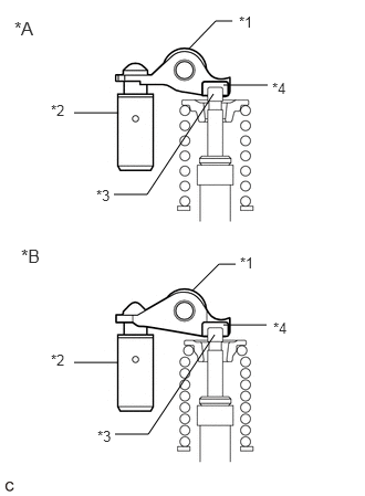
Install the 24 No. 1 valve rocker arm sub-assemblies as shown in the illustration.
| *A | Type A |
| *B | Type B |
| *1 | No. 1 Valve Rocker Arm Sub-assembly |
| *2 | Valve Lash Adjuster Assembly |
| *3 | Valve Stem |
| *4 | Valve Stem Cap |
30.INSTALL CAMSHAFT BEARING CAP (for Bank 1)
Apply engine oil to the camshaft journals, camshaft housing sub-assembly RH and camshaft bearing caps.
Install the camshaft and No. 2 camshaft to the camshaft housing sub-assembly RH.
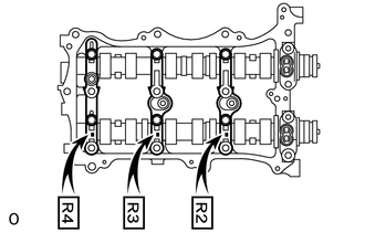
Confirm the marks and numbers on the camshaft bearing caps and place them in each proper position and direction.
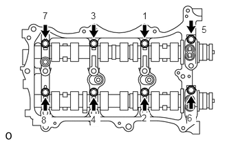
Temporarily tighten the 8 bolts in the order shown in the illustration.
- Torque:
- 10 N*m (102 kgf*cm, 7 ft.*lbf)
11103C
31.INSTALL CAMSHAFT HOUSING SUB-ASSEMBLY RH
- HINT:
-
0.052,0.063 1.698,4.5 1.646,4.438 1.781,0.063 3.385,4.5 1.604,4.438 1.146,2.094 1.146,2.354 false 2.854,2.083 2.854,2.344 false 2.604,2.979 2.885,2.979 false 0.896,3.01 1.167,3.01 false 0.958,3.802 1.229,3.802 false 2.656,3.885 2.927,3.885 false 0.104,0.083 0.5,0.333 0.396,0.25 12 false *A 1.833,0.083 2.229,0.333 0.396,0.25 12 false *B 1.396,0.885 1.667,1.125 0.271,0.24 10 false *b 3.125,0.875 3.344,1.115 0.219,0.24 10 false *b 1.042,2.354 1.313,2.594 0.271,0.24 10 false *1 2.771,2.354 3.042,2.594 0.271,0.24 10 false *1 0.615,2.458 0.885,2.698 0.271,0.24 10 false *a 2.344,2.479 2.615,2.719 0.271,0.24 10 false *a 2.917,2.896 3.188,3.135 0.271,0.24 10 false *2 1.229,2.917 1.5,3.156 0.271,0.24 10 false *2 1.281,3.708 1.552,3.948 0.271,0.24 10 false *3 2.99,3.781 3.26,4.021 0.271,0.24 10 false *3
-
Type A and Type B can be distinguished by the shape of the compression spring.
Text in Illustration *A Type A *B Type B *1 No. 1 Valve Rocker Arm Sub-assembly *2 Valve Spring Retainer *3 Inner Compression Spring *a Valve Spring Retainer Diameter *b No. 1 Valve Rocker Arm Sub-assembly Roller Width
Type No. 1 Valve Rocker Arm Sub-assembly Roller Width Valve Spring Retainer Diameter Inner Compression Spring Shape A 10.7 mm (0.421 in.) 23.4 mm (0.921 in.) Straight B 8.0 mm (0.315 in.) 18.9 mm (0.744 in.) Taper
Make sure that the No. 1 valve rocker arm sub-assembly is installed as shown in the illustration.
| *A | Type A |
| *B | Type B |
| *1 | No. 1 Valve Rocker Arm Sub-assembly |
| *2 | Valve Lash Adjuster Assembly |
| *3 | Valve Stem |
| *4 | Valve Stem Cap |
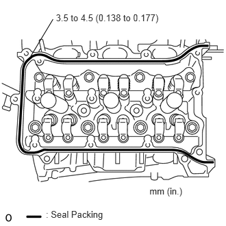
Apply seal packing in a continuous line as shown in the illustration.
- Seal Packing:
Toyota Genuine Seal Packing Black, Three Bond 1207B or equivalent
- Seal Diameter:
3.5 to 4.5 mm (0.138 to 0.177 in.)
- NOTICE:
- ·
Remove any oil from the contact surface.
·Install the camshaft housing sub-assembly RH within 3 minutes.
·Do not start the engine for at least 2 hours after installation.
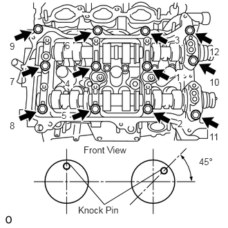
Install the camshaft housing sub-assembly RH and tighten the 12 bearing cap bolts in the order shown in the illustration.
- Torque:
- 28 N*m (286 kgf*cm, 21 ft.*lbf)
- NOTICE:
- ·
When installing the camshaft housing sub-assembly RH, it is necessary to correctly position the camshafts as shown in the illustration. Failure to do so may result in damage due to contact between the pistons and valves. If a camshaft is rotated with a piston at TDC, valve contact will occur.
·If any of the bolts are loosened during installation, remove the camshaft housing sub-assembly RH, clean the contact surfaces, and reapply seal packing.
·If the camshaft housing sub-assembly RH is removed because any of the bolts are loosened during installation, make sure that the previously applied seal packing does not enter any oil passages.
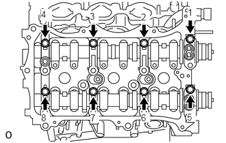
Tighten the 8 bolts in the order shown in the illustration.
- Torque:
- 16 N*m (163 kgf*cm, 12 ft.*lbf)
32.INSTALL CAMSHAFT BEARING CAP (for Bank 2)
Apply engine oil to the camshaft journals, camshaft housing sub-assembly LH and camshaft bearing caps.
Install the No. 3 camshaft and No. 4 camshaft to the camshaft housing sub-assembly LH.
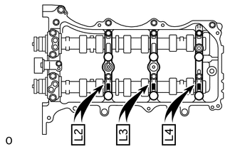
Confirm the marks and numbers on the camshaft bearing caps and place them in each proper position and direction.
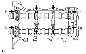
Temporarily tighten the 8 bolts in the order shown in the illustration.
- Torque:
- 10 N*m (102 kgf*cm, 7 ft.*lbf)
11104A
33.INSTALL CAMSHAFT HOUSING SUB-ASSEMBLY LH
- HINT:
-
0.052,0.063 1.698,4.5 1.646,4.438 1.781,0.063 3.385,4.5 1.604,4.438 1.146,2.094 1.146,2.354 false 2.854,2.083 2.854,2.344 false 2.604,2.979 2.885,2.979 false 0.896,3.01 1.167,3.01 false 0.958,3.802 1.229,3.802 false 2.656,3.885 2.927,3.885 false 0.104,0.083 0.5,0.333 0.396,0.25 12 false *A 1.833,0.083 2.229,0.333 0.396,0.25 12 false *B 1.396,0.885 1.667,1.125 0.271,0.24 10 false *b 3.125,0.875 3.344,1.115 0.219,0.24 10 false *b 1.042,2.354 1.313,2.594 0.271,0.24 10 false *1 2.771,2.354 3.042,2.594 0.271,0.24 10 false *1 0.615,2.458 0.885,2.698 0.271,0.24 10 false *a 2.344,2.479 2.615,2.719 0.271,0.24 10 false *a 2.917,2.896 3.188,3.135 0.271,0.24 10 false *2 1.229,2.917 1.5,3.156 0.271,0.24 10 false *2 1.281,3.708 1.552,3.948 0.271,0.24 10 false *3 2.99,3.781 3.26,4.021 0.271,0.24 10 false *3
-
Type A and Type B can be distinguished by the shape of the compression spring.
Text in Illustration *A Type A *B Type B *1 No. 1 Valve Rocker Arm Sub-assembly *2 Valve Spring Retainer *3 Inner Compression Spring *a Valve Spring Retainer Diameter *b No. 1 Valve Rocker Arm Sub-assembly Roller Width
Type No. 1 Valve Rocker Arm Sub-assembly Roller Width Valve Spring Retainer Diameter Inner Compression Spring Shape A 10.7 mm (0.421 in.) 23.4 mm (0.921 in.) Straight B 8.0 mm (0.315 in.) 18.9 mm (0.744 in.) Taper
Make sure that the No. 1 valve rocker arm sub-assembly is installed as shown in the illustration.
| *A | Type A |
| *B | Type B |
| *1 | No. 1 Valve Rocker Arm Sub-assembly |
| *2 | Valve Lash Adjuster Assembly |
| *3 | Valve Stem |
| *4 | Valve Stem Cap |
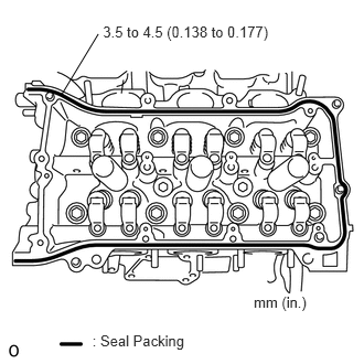
Apply seal packing in a continuous line as shown in the illustration.
- Seal Packing:
Toyota Genuine Seal Packing Black, Three Bond 1207B or equivalent
- Seal Diameter:
3.5 to 4.5 mm (0.138 to 0.177 in.)
- NOTICE:
- ·
Remove any oil from the contact surface.
·Install the camshaft housing sub-assembly LH within 3 minutes.
·Do not start the engine for at least 2 hours after installation.
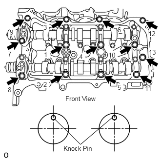
Install the camshaft housing sub-assembly LH and tighten the 13 bearing cap bolts in the order shown in the illustration.
- Torque:
- 28 N*m (286 kgf*cm, 21 ft.*lbf)
- NOTICE:
- ·
When installing the camshaft housing sub-assembly LH, it is necessary to correctly position the camshafts as shown in the illustration. Failure to do so may result in damage due to contact between the pistons and valves. If a camshaft is rotated with a piston at TDC, valve contact will occur.
·If any of the bolts are loosened during installation, remove the camshaft housing sub-assembly LH, clean the contact surfaces, and reapply seal packing.
·If the camshaft housing sub-assembly LH is removed because any of the bolts are loosened during installation, make sure that the previously applied seal packing does not enter any oil passages.
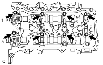
Tighten the 8 bolts in the order shown in the illustration.
- Torque:
- 16 N*m (163 kgf*cm, 12 ft.*lbf)
13550
34.INSTALL NO. 2 CHAIN TENSIONER ASSEMBLY
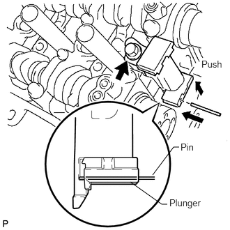
Install the No. 2 chain tensioner assembly with the bolt.
- Torque:
- 21 N*m (214 kgf*cm, 15 ft.*lbf)
While pushing in the No. 2 chain tensioner assembly, insert a pin of 1.0 mm (0.039 in.) diameter into the hole to secure it.
35.INSTALL CAMSHAFT TIMING GEARS AND NO. 2 CHAIN (for Bank 1)
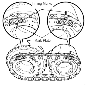
Align the mark plate (yellow) with the timing marks (1-dot mark) of the camshaft timing gear sub-assembly and camshaft timing exhaust gear assembly RH as shown in the illustration.
Apply a light coat of engine oil to the bolt threads and the bottom of the bolt heads.
Align the knock pin of the camshaft with the pin hole of the camshaft timing gear sub-assembly. Install the camshaft timing gear assembly and camshaft timing exhaust gear assembly RH with the No. 2 chain sub-assembly installed.
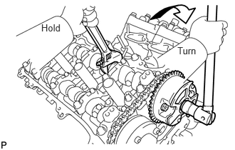
Hold the hexagonal portion of the camshaft with a wrench, and tighten the 2 bolts, camshaft timing gear assembly and camshaft timing exhaust gear assembly RH.
T = 100 N*m{ 1,020 kgf*cm 74 ft.*lbf }
Remove the pin from the No. 2 chain tensioner assembly.
13560A
36.INSTALL NO. 3 CHAIN TENSIONER ASSEMBLY
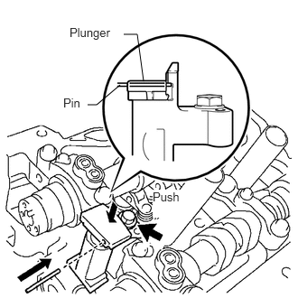
Install the No. 3 chain tensioner assembly with the bolt.
- Torque:
- 21 N*m (214 kgf*cm, 15 ft.*lbf)
While pushing in the No. 3 chain tensioner assembly, insert a pin of 1.0 mm (0.039 in.) diameter into the hole to secure it.
37.INSTALL CAMSHAFT TIMING GEARS AND NO. 2 CHAIN (for Bank 2)
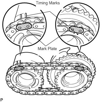
Align the mark plate (yellow) with the timing marks (2-dot mark) of the camshaft timing gear assembly and camshaft timing exhaust gear assembly LH as shown in the illustration.
Apply a light coat of engine oil to the bolt threads and the bottom of the bolt heads.
Align the knock pin of the camshaft with the pin hole of the camshaft timing gear assembly. Install the camshaft timing gear assembly and camshaft timing exhaust gear assembly LH with the No. 2 chain sub-assembly installed.
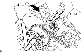
Hold the hexagonal portion of the camshaft with a wrench, and tighten the 2 bolts, camshaft timing gear assembly and camshaft timing exhaust gear assembly LH.
T = 100 N*m{ 1,020 kgf*cm 74 ft.*lbf }
Remove the pin from the No. 3 chain tensioner assembly.
13561
38.INSTALL NO. 1 CHAIN VIBRATION DAMPER
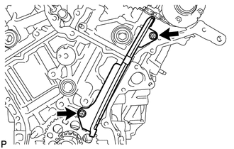
Install the No. 1 chain vibration damper with the 2 bolts.
- Torque:
- 23 N*m (230 kgf*cm, 17 ft.*lbf)
13562
39.INSTALL NO. 2 CHAIN VIBRATION DAMPER
Install the 2 No. 2 chain vibration dampers.
13521
40.INSTALL CRANKSHAFT TIMING SPROCKET
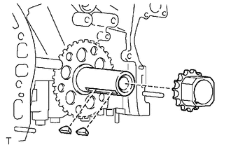
Install the 2 keys and crankshaft timing sprocket as shown in the illustration.
13530
41.INSTALL IDLE SPROCKET ASSEMBLY
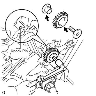
Apply a light coat of engine oil to the rotating surface of the No. 1 idle gear shaft.
Temporarily install the No. 1 idle gear shaft and idle sprocket assembly with the No. 2 idle gear shaft while aligning the knock pin of the No. 1 idle gear shaft with the knock pin groove of the cylinder block sub-assembly.
- NOTICE:
-
Be careful of the idle gear orientation.
- HINT:
-
Check that no foreign matter is on the No. 1 idle gear shaft and No. 2 idle gear shaft.
Using a 10 mm hexagon wrench, tighten the No. 2 idle gear shaft.
- Torque:
- 60 N*m (612 kgf*cm, 44 ft.*lbf)
- HINT:
-
After installing the idle sprocket assembly, check that the idle sprocket assembly turns smoothly.
13506
42.INSTALL CHAIN SUB-ASSEMBLY
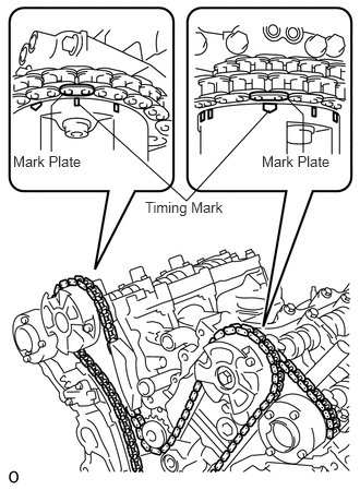
Align the mark plate and timing marks as shown in the illustration and install the chain sub-assembly.
- HINT:
-
The camshaft mark plate is orange.
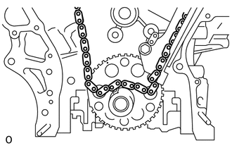
Do not pass the chain sub-assembly over the crankshaft, just temporarily place it on the crankshaft.
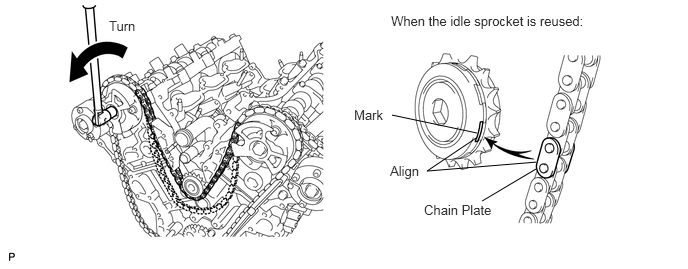
Turn the camshaft timing gear assembly on the bank 1 counterclockwise to tighten the chain sub-assembly between the banks.
- NOTICE:
-
When the idle sprocket assembly is reused, align the chain plate with the mark where the plate had been in order to tighten the chain sub-assembly between the banks.
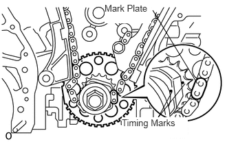
Align the mark plate and timing marks as shown in the illustration and install the chain sub-assembly onto the crankshaft timing sprocket.
- HINT:
-
The crankshaft mark plate is yellow.
Temporarily tighten the pulley set bolt.
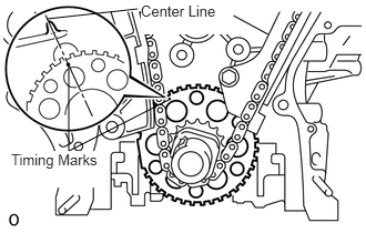
Turn the crankshaft clockwise to set it to the RH block bore center line (TDC/compression).
13559
43.INSTALL CHAIN TENSIONER SLIPPER
Install the chain tensioner slipper.
13540
44.INSTALL NO. 1 CHAIN TENSIONER ASSEMBLY
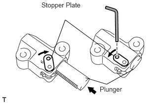
Move the stopper plate upward to release the lock, and push the plunger deep into the No. 1 chain tensioner assembly.
Move the stopper plate downward to set the lock, and insert a hexagon wrench into the hole of the stopper plate.
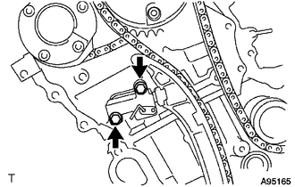
Install the No. 1 chain tensioner assembly with the 2 bolts.
- Torque:
- 10 N*m (102 kgf*cm, 7 ft.*lbf)
Remove the hexagon wrench of the No. 1 chain tensioner assembly. Check that each timing mark is aligned with the crankshaft at the TDC/compression.
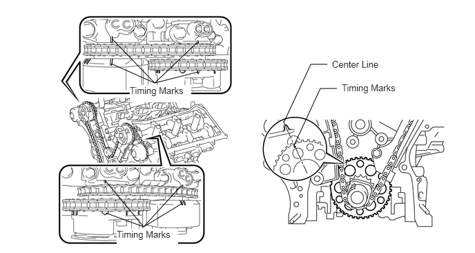
Remove the pulley set bolt.
11301C
45.INSTALL TIMING CHAIN CASE OIL SEAL
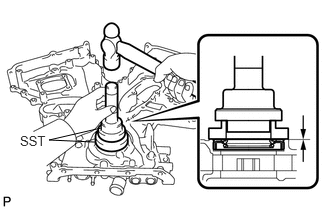
Using SST, tap in a new timing chain case oil seal until its surface is flush with the timing gear case edge.
- SST
- 09223-22010
09506-35010
- NOTICE:
- ·
Keep the lip free of foreign matter.
·Do not tap in the timing chain case oil seal at an angle.
·Make sure that the timing chain case oil seal edge does not stick out of the timing chain case.
16100
46.INSTALL WATER PUMP ASSEMBLY
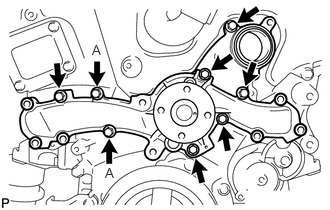
Install a new gasket and the water pump assembly with the 8 bolts.
- Torque:
- 9.1 N*m (93 kgf*cm, 81 in.*lbf)
- NOTICE:
-
Be sure to replace the bolts (A) with new ones or reuse them after applying adhesive 1344.
11302
47.INSTALL TIMING CHAIN COVER SUB-ASSEMBLY
Apply seal packing in a continuous line to the engine unit as shown in the following illustration.
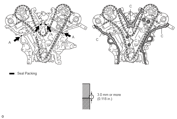
- Seal Packing:
Toyota Genuine Seal Packing Black, Three Bond 1207B or equivalent
- Seal Diameter:
3.0 mm (0.118 in.) or more
- NOTICE:
- ·
Be sure to clean the contact surfaces, especially the surfaces (C).
·When there is oil on the contact surfaces, wipe them with an oil-free cloth before applying seal packing.
·Install the timing chain cover sub-assembly within 3 minutes.
·Do not start the engine for at least 2 hours after installation.
Apply seal packing in a continuous line to the timing chain cover sub-assembly as shown in the following illustration.
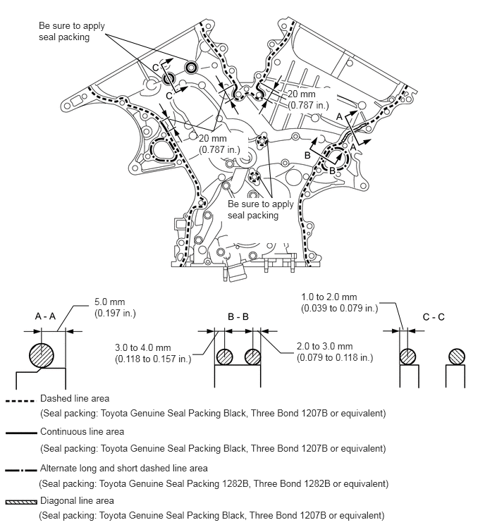
- Seal Packing:
Toyota Genuine Seal Packing Black, Three Bond 1207B or equivalent
Toyota Genuine Seal Packing Black 1282B, Three Bond 1282B or equivalent
- NOTICE:
- ·
When there is oil on the contact surfaces, wipe them with an oil-free cloth before applying seal packing.
·Install the timing chain cover sub-assembly within 3 minutes and tighten the bolts within 15 minutes after applying seal packing.
·Do not start the engine for at least 2 hours after installation.
- Apply Seal Packing as Follows:
Area Seal Packing Diameter Application Position from Inside Seal Line Continuous Line Area 4.5 mm or more (0.177 in.) 3.0 to 4.0 mm (0.118 to 0.157 in.) Alternate Long and Dashed Line Area 3.5 mm or more (0.138 in.) 2.0 to 3.0 mm (0.079 to 0.118 in.) Dashed Line Area 3.5 mm or more (0.138 in.) 3.0 to 4.0 mm (0.118 to 0.157 in.) Diagonal Line Area 6.0 mm or more (0.236 in.) 5.0 mm (0.197 in.)
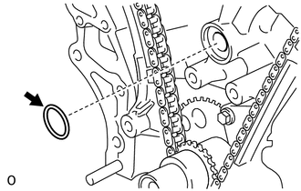
Install a new gasket.
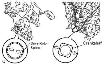
Align the drive rotor spline of the oil pump and the crankshaft as shown in the illustration. Install the spline and timing chain cover sub-assembly to the crankshaft.
Type X:
Temporarily tighten the timing chain cover sub-assembly with the 23 bolts and 2 nuts.
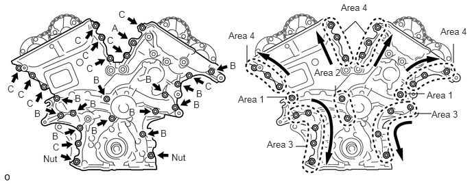
- Bolt Length:
Item Length Bolt A 40 mm (1.57 in.) Bolt B 55 mm (2.17 in.) Bolt C 25 mm (0.98 in.)
- NOTICE:
-
Make sure that there is no oil on the bolt and nut threads.
Type Y:
Temporarily tighten the timing chain cover sub-assembly with the 23 bolts and 2 nuts.
- Bolt Length:
Item Length Bolt A 40 mm (1.57 in.) Bolt B 55 mm (2.17 in.) Bolt C 28 mm (1.102 in.)
- NOTICE:
-
Make sure that there is no oil on the bolt and nut threads.
Fully tighten the bolts in this order: Area 1 and Area 2.
- Torque:
- 21 N*m (214 kgf*cm, 15 ft.*lbf)
Fully tighten the bolts in Area 3.
- Torque:
- 21 N*m (214 kgf*cm, 15 ft.*lbf)
- HINT:
-
Tighten the bolts and nuts in the order of upper to lower as shown in the illustration.
Fully tighten the bolts in Area 4.
- Torque:
- Bolt (A) : 43 N*m (438 kgf*cm, 32 ft.*lbf)
- Except Bolt (A) : 21 N*m (214 kgf*cm, 15 ft.*lbf)
- HINT:
-
Tighten the bolts in the order of lower to upper as shown in the illustration.
Install a new chain cover plate gasket and the chain cover plate with the 4 bolts.
- Torque:
- 9.1 N*m (93 kgf*cm, 81 in.*lbf)
16323
48.INSTALL WATER INLET HOUSING
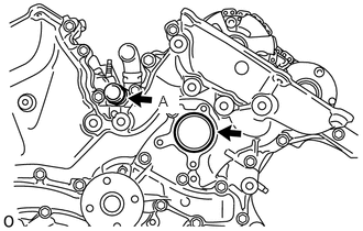
Install 2 new O-rings.
- HINT:
-
Apply a small amount of water or soapy water to the O-ring (A) before installing it.
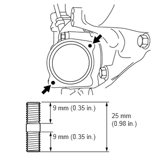
Install the 2 stud bolts.
- Torque:
- 4.0 N*m (41 kgf*cm, 35 in.*lbf)
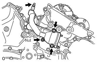
Install the water inlet housing with the 2 bolts and nut.
- Torque:
- 10 N*m (102 kgf*cm, 7 ft.*lbf)
- NOTICE:
-
Be careful that the O-ring does not get caught between the parts.
Connect the No. 1 water by-pass hose and slide the clip to secure it.
Apply adhesive around the drain cock plug.
- Adhesive:
Toyota Genuine Adhesive 1324, Three Bond 1324 or equivalent
Install the drain cock assembly to the water inlet housing.
- Torque:
- 30 N*m (306 kgf*cm, 22 ft.*lbf)
Install the drain cock plug to the drain cock assembly.
- Torque:
- 13 N*m (130 kgf*cm, 9 ft.*lbf)
Install a new gasket to the thermostat.
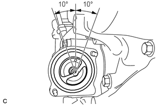
Align the thermostat jiggle valve with the upper stud bolt, and insert the thermostat in the water inlet housing.
- HINT:
-
The jiggle valve may be set within 10° of either side of the prescribed positions.
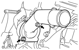
Install the water inlet with the 2 nuts.
- Torque:
- 10 N*m (102 kgf*cm, 7 ft.*lbf)
12315
49.INSTALL NO. 1 FRONT ENGINE MOUNTING BRACKET LH
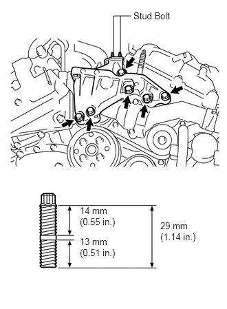
Install the No. 1 front engine mounting bracket LH with the 6 bolts.
- Torque:
- 54 N*m (551 kgf*cm, 40 ft.*lbf)
- NOTICE:
- ·
Install the water inlet and front No. 1 engine mounting bracket LH within 15 minutes of installing the timing chain cover sub-assembly.
·Do not start the engine for at least 2 hours after installation.
Using an E8 "TORX" socket wrench, install the 2 stud bolts.
- Torque:
- 10 N*m (102 kgf*cm, 7 ft.*lbf)
12121
50.INSTALL NO. 1 OIL PAN BAFFLE PLATE
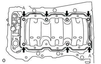
Install the No. 1 oil pan baffle plate with the 7 bolts.
- Torque:
- 10 N*m (102 kgf*cm, 7 ft.*lbf)
- HINT:
-
Temporarily tighten the 7 bolts. Fully tighten the 2 bolts (A) before tightening the other bolts.
12101
51.INSTALL OIL PAN SUB-ASSEMBLY
Using an E8 "TORX" socket wrench, install the 2 stud bolts.
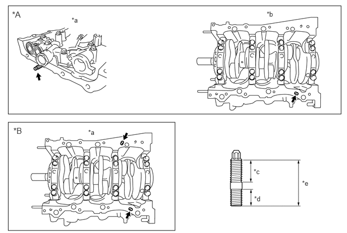
| *A | Type A | *B | Type B |
| *a | Timing Chain Cover Sub-assembly Side | *b | Cylinder Block Sub-assembly Bottom Side |
| *c | 16 mm (0.63 in.) | *d | 12 mm (0.47 in.) |
| *e | 34 mm (1.34 in.) | - | - |
- Torque:
- 10 N*m (102 kgf*cm, 7 ft.*lbf)
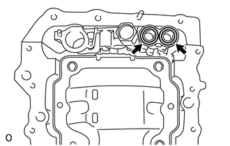
Install 2 new O-rings.
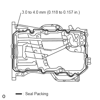
Apply seal packing in a continuous line as shown in the illustration.
- Seal Packing:
Toyota Genuine Seal Packing Black, Three Bond 1207B or equivalent
- Seal Diameter:
3.0 to 4.0 mm (0.118 to 0.157 in.)
- NOTICE:
- ·
Remove any oil from the contact surface.
·Install the oil pan sub-assembly within 3 minutes after applying seal packing.
·Do not start the engine for at least 2 hours after installation.
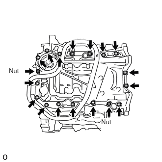
Install the oil pan sub-assembly with the 16 bolts and 2 nuts.
- Torque:
- Bolt (A) : 10 N*m (102 kgf*cm, 7 ft.*lbf)
- Except Bolt (B) : 21 N*m (214 kgf*cm, 15 ft.*lbf)
15104
52.INSTALL OIL STRAINER SUB-ASSEMBLY
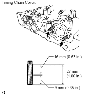
Using an E6 "TORX" socket wrench, install the 2 stud bolts as shown in the illustration.
- Torque:
- 4.0 N*m (41 kgf*cm, 35 in.*lbf)
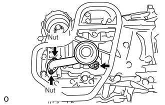
Install a new gasket and the oil strainer sub-assembly with the bolt and 2 nuts.
- Torque:
- 10 N*m (102 kgf*cm, 7 ft.*lbf)
12102A
53.INSTALL NO. 2 OIL PAN SUB-ASSEMBLY
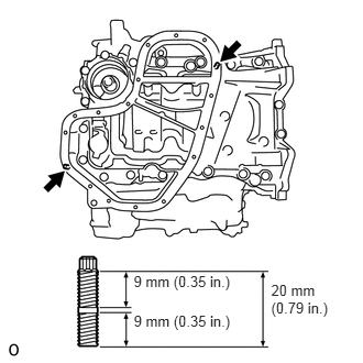
Using an E6 "TORX" socket wrench, install the 2 stud bolts as shown in the illustration.
- Torque:
- 4.0 N*m (41 kgf*cm, 35 in.*lbf)
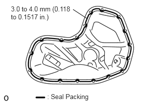
Apply seal packing in a continuous line as shown in the illustration.
- Seal Packing:
Toyota Genuine Seal Packing Black, Three Bond 1207B or equivalent
- Seal Diameter:
3.0 to 4.0 mm (0.118 to 0.157 in.)
- NOTICE:
- ·
Remove any oil from the contact surface.
·Install the No. 2 oil pan sub-assembly within 3 minutes after applying seal packing.
·Do not start the engine for at least 2 hours after installation.
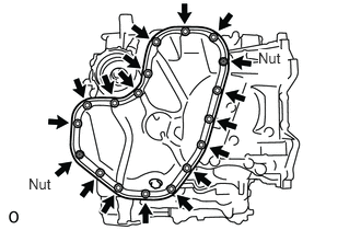
Install the No. 2 oil pan sub-assembly with the 16 bolts and 2 nuts.
- Torque:
- 10 N*m (102 kgf*cm, 7 ft.*lbf)
12101A
54.INSTALL OIL PAN DRAIN PLUG
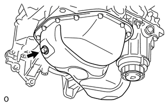
Install a new oil pan drain plug gasket and the oil pan drain plug.
- Torque:
- 40 N*m (408 kgf*cm, 30 ft.*lbf)
11201
55.INSTALL CYLINDER HEAD COVER SUB-ASSEMBLY (for Bank 1)
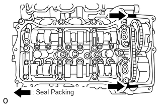
Apply seal packing as shown in the illustration.
- Seal Packing:
Toyota Genuine Seal Packing Black, Three Bond 1207B or equivalent
- NOTICE:
- ·
Remove any oil from the contact surface.
·Install the cylinder head cover sub-assembly within 3 minutes after applying seal packing.
·Do not start the engine for at least 2 hours after installation.
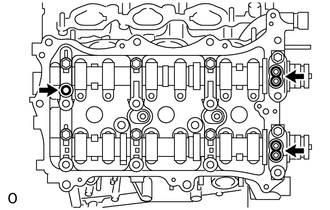
Install 3 new gaskets as shown in the illustration.
Install a new cylinder head cover gasket to the cylinder head cover sub-assembly.
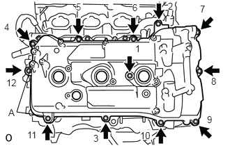
Install the cylinder head cover sub-assembly with the 12 bolts and a new seal washer.
- Torque:
- Bolt (A) : 21 N*m (214 kgf*cm, 15 ft.*lbf)
- Except Bolt (A) : 10 N*m (102 kgf*cm, 7 ft.*lbf)
- HINT:
-
After tightening all bolts, check the tightening torque of 1 and 11. Retighten the bolt if necessary.
11201
56.INSTALL CYLINDER HEAD COVER SUB-ASSEMBLY (for Bank 2)
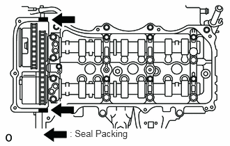
Apply seal packing as shown in the illustration.
- Seal Packing:
Toyota Genuine Seal Packing Black, Three Bond 1207B or equivalent
- NOTICE:
- ·
Remove any oil from the contact surface.
·Install the cylinder head cover sub-assembly within 3 minutes of applying seal packing.
·Do not start the engine for at least 2 hours after installation.
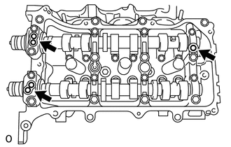
Install 3 new gaskets as shown in the illustration.
Install a new cylinder head cover gasket to the cylinder head cover sub-assembly.
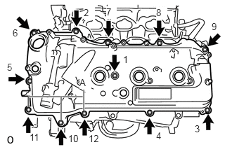
Install the cylinder head cover sub-assembly with the 12 bolts and a new seal washer.
- Torque:
- Bolt (A) : 21 N*m (214 kgf*cm, 15 ft.*lbf)
- Except Bolt (A) : 10 N*m (102 kgf*cm, 7 ft.*lbf)
- HINT:
-
After tightening all bolts, check the tightening torque of 1 and 10. Retighten the bolt if necessary.
16331
57.INSTALL WATER OUTLET
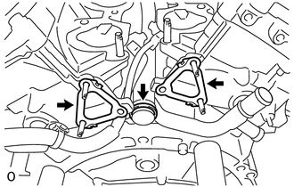
Install 2 new gaskets and a new O-ring.
- HINT:
-
Apply soapy water to the O-ring.
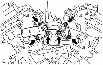
Install the water outlet with the 2 bolts and 4 nuts.
- Torque:
- 10 N*m (102 kgf*cm, 7 ft.*lbf)
- NOTICE:
-
Be careful that the O-ring does not get caught between the parts.
13471
58.INSTALL CRANKSHAFT PULLEY
Align the crankshaft pulley set key with the key groove of the crankshaft pulley, and slide on the crankshaft pulley.
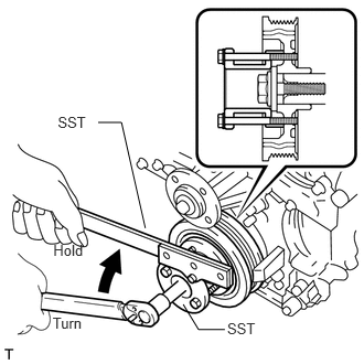
Using SST, install the pulley bolt.
- SST
- 09213-70011 (09213-70020)
09330-00021
T = 250 N*m{ 2,550 kgf*cm 184 ft.*lbf }
04152
59.INSTALL OIL FILTER SUB-ASSEMBLY
11415
60.INSTALL CYLINDER BLOCK WATER DRAIN COCK SUB-ASSEMBLY
for Bank 1:
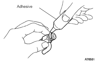
Apply adhesive to the cylinder block water drain cock sub-assembly.
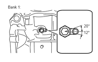
Install the cylinder block water drain cock sub-assembly as shown in the illustration.
- Torque:
- 25 N*m (255 kgf*cm, 18 ft.*lbf)
- NOTICE:
-
Do not rotate the cylinder block water drain cock sub-assembly more than 1 revolution (360°) after tightening the cylinder block water drain cock sub-assembly to the specified torque.
Install the cylinder block water drain cock plug to the cylinder block water drain cock sub-assembly.
- Torque:
- 13 N*m (130 kgf*cm, 9 ft.*lbf)
for Bank 2:
- HINT:
-
Perform this operation only when a cylinder block water drain cock sub-assembly is installed.
Apply adhesive to the cylinder block water drain cock sub-assembly.
- Adhesive:
Toyota Genuine Adhesive 1324, Three Bond 1324 or equivalent
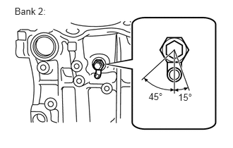
Install the cylinder block water drain cock sub-assembly as shown in the illustration.
- Torque:
- 25 N*m (255 kgf*cm, 18 ft.*lbf)
- NOTICE:
-
Do not rotate the cylinder block water drain cock sub-assembly more than 1 revolution (360°) after tightening the cylinder block water drain cock sub-assembly to the specified torque.
Install the cylinder block water drain cock plug to the cylinder block water drain cock sub-assembly.
- Torque:
- 13 N*m (130 kgf*cm, 9 ft.*lbf)
11415
61.INSTALL TAPER SCREW PLUG
- HINT:
-
Perform this operation only when a taper screw plug is installed
Apply adhesive to the taper screw plug.
Install the taper screw plug to the cylinder block sub-assembly.
- Torque:
- 13 N*m (130 kgf*cm, 9 ft.*lbf)
15771
62.INSTALL NO. 1 OIL PIPE
Make sure that there is no foreign matter on the mesh of the oil control valve filter LH.
- NOTICE:
-
Do not touch the mesh when installing the oil control valve filter LH.
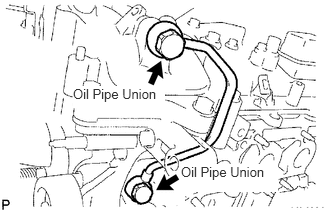
Install the oil control valve filter LH to the oil pipe union. Install 2 new gaskets and temporarily install the No. 1 oil pipe (on the cylinder head cover sub-assembly side).
Install a new gasket and temporarily install the No. 1 oil pipe (on the cylinder head sub-assembly side) with the oil check valve bolt.
Tighten the oil pipe union (on the cylinder head cover sub-assembly side).
- Torque:
- 65 N*m (663 kgf*cm, 48 ft.*lbf)
Tighten the oil pipe union (on the cylinder head sub-assembly side).
- Torque:
- 65 N*m (663 kgf*cm, 48 ft.*lbf)
- NOTICE:
-
If the link that connects the gaskets is broken, remove the connecting link by using nippers or similar tools.
15771M
63.INSTALL OIL PIPE
Make sure that there is no foreign matter on the mesh of the oil control valve filter RH.
- NOTICE:
-
Do not touch the mesh when installing the oil control valve filter RH.
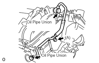
Install the oil control valve filter RH to the oil pipe union. Install 2 new gaskets and temporarily install the oil pipe (on the cylinder head cover sub-assembly side).
Install a new gasket and temporarily install the oil pipe (on the cylinder head sub-assembly side) with the oil check valve bolt.
Install the bolt (A) to the cylinder head sub-assembly.
- Torque:
- 10 N*m (102 kgf*cm, 7 ft.*lbf)
Tighten the oil pipe union (on the head cover sub-assembly side).
- Torque:
- 65 N*m (663 kgf*cm, 48 ft.*lbf)
Tighten the oil pipe union (on the cylinder head sub-assembly side).
- Torque:
- 65 N*m (663 kgf*cm, 48 ft.*lbf)
- NOTICE:
-
If the link that connects the gaskets is broken, remove the connecting link by using nippers or similar tools.
11401G
64.INSTALL CRANKSHAFT POSITION SENSOR
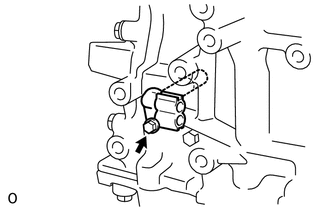
Install the crankshaft position sensor with the bolt.
- Torque:
- 10 N*m (102 kgf*cm, 7 ft.*lbf)
11101J
65.INSTALL CAMSHAFT TIMING OIL CONTROL VALVE ASSEMBLY
Install the 4 camshaft timing oil control valve assemblies with the 4 bolts.
- Torque:
- 10 N*m (102 kgf*cm, 7 ft.*lbf)
66.INSTALL CAMSHAFT POSITION SENSOR
Install the 4 camshaft position sensors with the 4 bolts.
- Torque:
- 10 N*m (102 kgf*cm, 7 ft.*lbf)
12204
67.INSTALL VENTILATION VALVE SUB-ASSEMBLY
Apply adhesive to the ventilation valve sub-assembly.
- Adhesive:
Toyota Genuine Adhesive 1324, Three Bond 1324 or equivalent
Install the ventilation valve sub-assembly.
- Torque:
- 27 N*m (275 kgf*cm, 20 ft.*lbf)
19100P
68.INSTALL SPARK PLUG
Install the 6 spark plugs.
- Torque:
- 18 N*m (184 kgf*cm, 13 ft.*lbf)
15620
69.INSTALL OIL FILLER CAP SUB-ASSEMBLY
Install a new oil filler cap gasket.
Install the oil filler cap sub-assembly.