2GR-FE COOLING COOLING FAN ECU ON-VEHICLE INSPECTION
PROCEDURE

 89257
1.INSPECT NO. 1 COOLING FAN ECU
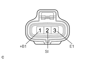
Inspect the input voltage.
Disconnect the No. 1 cooling fan ECU connector.
Turn the ignition switch to the ON position. Check the voltage of the +B terminal of the disconnected wire harness side connector.
- Standard voltage:
9 to 14 V
If the result is not as specified, inspect the power source system (fusible link, fuse, wire harness and relay).
Inspect the No. 1 cooling fan motor (See page Engine / Hybrid System>2GR-FE COOLING>COOLING FAN MOTOR>ON-VEHICLE INSPECTION).
Measure the resistance between terminals RFC (ECM) and SI (No. 1 cooling fan ECU) of the wire harness side connectors.
- HINT:
- ·
If the fan does not operate, there may be a short circuit.
·If the fan remains operating, there may be an open circuit.
Inspect the ECM power source circuit and ground circuit.
89257
2.INSPECT NO. 2 COOLING FAN ECU
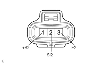
Inspect the input voltage.
Disconnect the No. 2 cooling fan ECU connector.
Turn the ignition switch to the ON position. Check the voltage of the +B terminal of the disconnected wire harness side connector.
- Standard voltage:
9 to 14 V
If the result is not as specified, inspect the power source system (fusible link, fuse, wire harness and relay).
Inspect the No. 2 cooling fan motor (See page Engine / Hybrid System>2GR-FE COOLING>COOLING FAN MOTOR>ON-VEHICLE INSPECTION).
Measure the resistance between terminals RFC (ECM) and SI2 (No. 2 cooling fan ECU) of the wire harness side connectors.
- HINT:
- ·
If the fan does not operate, there may be a short circuit.
·If the fan remains operating, there may be an open circuit.
Inspect the ECM power source circuit and ground circuit.