BRAKE BRAKE MASTER CYLINDER(for RHD) INSTALLATION
PROCEDURE

 47201
1.INSTALL BRAKE MASTER CYLINDER SUB-ASSEMBLY
- NOTICE:
- ·
The master cylinder and piston are designed so that the piston can easily fall out. Prevent this by making sure that the tip of the master cylinder points downward when handling the master cylinder.
·Make sure foreign matter does not attach to the master cylinder's piston. If foreign matter attaches, clean it off with a cloth. Then apply lithium soap base glycol grease to the entire outer circumference contact surface area of the piston.
Install a new O-ring to the master cylinder.
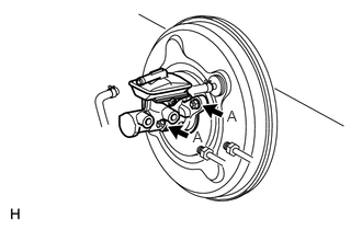
Install the master cylinder to the booster with the 2 nuts (labeled A).
- Torque:
- 13 N*m (130 kgf*cm, 9 ft.*lbf)
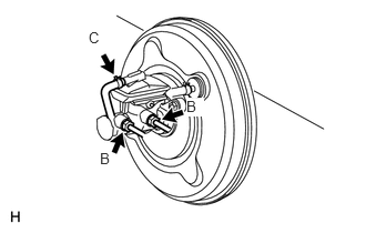
Using SST, connect the 2 brake lines (labeled B) to the master cylinder.
- SST
- 09023-00101
09023-38201
- Torque:
- w/o VSC : 15 N*m (155 kgf*cm, 11 ft.*lbf)
without SST
- 14 N*m (144 kgf*cm, 10 ft.*lbf)
with SST
- Torque:
- w/ VSC : 20 N*m (199 kgf*cm, 14 ft.*lbf)
without SST
- 18 N*m (185 kgf*cm, 13 ft.*lbf)
with SST
- HINT:
- ·
Use a torque wrench with a fulcrum length of 30 cm (11.81 in.).
·This torque value is effective when SST is parallel to a torque wrench.
Connect the No. 1 reservoir tube (labeled C) to the master cylinder.
44781D
2.INSTALL RESERVOIR HOSE BRACKET
Install the bracket with the nut.
- Torque:
- 5.4 N*m (55 kgf*cm, 48 in.*lbf)
Install the No. 1 reservoir tube to the clamps of the bracket.
47202
3.INSTALL BRAKE MASTER CYLINDER RESERVOIR SUB-ASSEMBLY
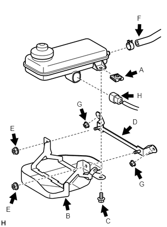
Install the nut (labeled A) to the reservoir.
Install the reservoir to the reservoir bracket (labeled B) with the bolt (labeled C).
- Torque:
- 8.8 N*m (90 kgf*cm, 78 in.*lbf)
Install the reservoir bracket (labeled D) to the reservoir with bracket with the 2 nuts (labeled E).
- Torque:
- 8.8 N*m (90 kgf*cm, 78 in.*lbf)
Connect the No. 1 reservoir tube (labeled F) to the reservoir.
Install the reservoir with brackets with the 2 nuts (labeled G).
- Torque:
- 8.8 N*m (90 kgf*cm, 78 in.*lbf)
Connect the brake fluid level warning switch connector (labeled H) to the reservoir.
4.BLEED BRAKE SYSTEM
(See page Brake>BRAKE>BRAKE FLUID>BLEEDING)