BRAKE FRONT BRAKE FLEXIBLE HOSE INSTALLATION
CAUTION / NOTICE / HINT
- HINT:
- ·
Use the same procedures for the LH side and RH side.
·The procedures listed below are for the LH side.
PROCEDURE

 47313A
1.INSTALL FRONT FLEXIBLE HOSE
- NOTICE:
- ·
Because the left and right hoses are not interchangeable, verify the part number when installing the flexible hose.
·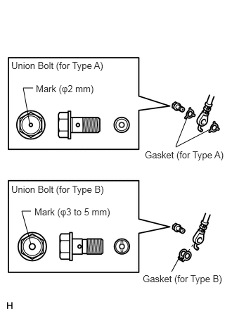 0.438,1.823 0.344,1.302 false 0.344,1.302 0.49,1.302 false 0.458,3.615 0.323,3.125 false 0.323,3.125 0.458,3.125 false 2.802,1.667 2.604,2.167 false 2.604,2.177 3.125,1.906 false 2.667,3.792 2.542,4.021 false 2.146,2.208 3.354,2.438 1.208,0.229 10 false Gasket (for Type A) 0.167,0.885 1.698,1.094 1.531,0.208 10 false Union Bolt (for Type A) 0.167,2.719 1.698,2.927 1.531,0.208 10 false Union Bolt (for Type B) 2.115,4.042 3.302,4.24 1.188,0.198 10 false Gasket (for Type B) 0.531,1.229 1.677,1.427 1.146,0.198 10 false Mark (φ2 mm) 0.51,3.052 1.76,3.25 1.25,0.198 10 false Mark (φ3 to 5 mm)
The gasket and union bolt must be used as a set, as shown in the illustration.
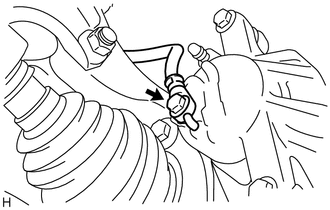
Connect the flexible hose with new gasket(s) and a new union bolt to the disc brake cylinder.
- Torque:
- 29 N*m (300 kgf*cm, 22 ft.*lbf)
- HINT:
-
Install the flexible hose lock securely in the lock hole in the cylinder.
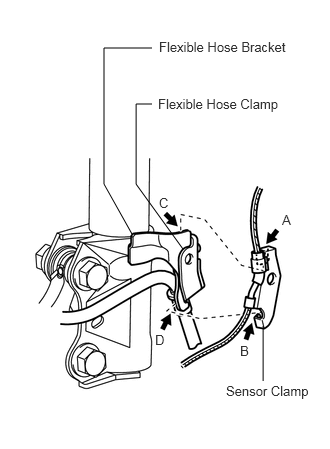
Set the flexible hose clamp on the flexible hose bracket.
Simultaneously perform the following: 1) hang the hook part of the sensor clamp (labeled A) on the flexible hose bracket (labeled C); and 2) insert the hook part of the sensor clamp (labeled B) into the flexible hose bracket (labeled D).
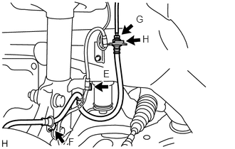
Tighten the bolt (labeled E) to fix the flexible hose clamp and sensor clamp.
- Torque:
- 19 N*m (189 kgf*cm, 14 ft.*lbf)
Install the flexible hose with the bolt (labeled F).
- Torque:
- 19 N*m (189 kgf*cm, 14 ft.*lbf)
Set the flexible hose to the connecting point with the brake tube (labeled G), and then attach a new clip (labeled H).
Using SST, connect the flexible hose to the brake tube (labeled G) while holding the flexible hose with a wrench.
- SST
- 09023-00101
- Torque:
- 15 N*m (155 kgf*cm, 11 ft.*lbf)
without SST
- 14 N*m (144 kgf*cm, 10 ft.*lbf)
with SST
- HINT:
- ·
Use a torque wrench with a fulcrum length of 30 cm (11.81 in.).
·This torque value is effective when SST is parallel to a torque wrench.
- NOTICE:
- ·
Do not bend or damage the brake tube.
·Do not allow any foreign matter such as dirt and dust to enter the brake tube from the connecting point.
2.FILL RESERVOIR WITH BRAKE FLUID
3.BLEED AIR FROM BRAKE MASTER CYLINDER
4.BLEED AIR FROM BRAKE LINE
5.CHECK BRAKE FLUID LEVEL IN RESERVOIR
6.INSPECT FOR BRAKE FLUID LEAK
7.INSTALL FRONT WHEEL
T = 103 N*m{ 1,050 kgf*cm 76 ft.*lbf }