PARKING BRAKE PARKING BRAKE ASSEMBLY REASSEMBLY
CAUTION / NOTICE / HINT
- HINT:
- ·
Use the same procedures for the LH side and RH side.
·The procedures listed below are for the LH side.
PROCEDURE

 1.APPLY HIGH TEMPERATURE GREASE
Apply high temperature grease to the contact surface of the shoe and backing plate (see page Brake>PARKING BRAKE>PARKING BRAKE ASSEMBLY>COMPONENTS).
47456A
2.INSTALL PARKING BRAKE SHOE GUIDE PLATE
Apply adhesive to the threads of the guide plate set bolt.
- Adhesive:
Toyota Genuine Adhesive 1344, Three Bond 1344 or equivalent
Install the guide plate with the guide plate set bolt.
- Torque:
- 18 N*m (184 kgf*cm, 13 ft.*lbf)
47612
3.INSTALL PARKING BRAKE SHOE LEVER LH
Apply high temperature grease to the contact surface of the parking brake lever pin of the shoe.
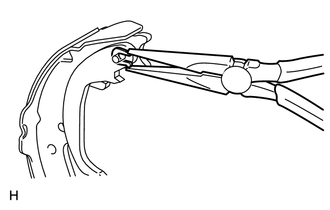
Using needle-nose pliers, install the parking brake lever to the shoe with a new C-washer.
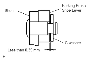
Using a thickness gauge, measure the clearance between the parking brake shoe lever and C-washer.
- OK:
Less than 0.35 mm (0.0138 in.)
If the value does not meet the specified value, select an appropriate shim so that the clearance will meet the specified value.
- Standard shim thickness:
Part No. Standard Condition 90564-09184 0.3 mm (0.0118 in.) 90564-09185 0.6 mm (0.0236 in.) 90564-09186 0.9 mm (0.0354 in.)
46590
4.INSTALL NO. 2 PARKING BRAKE SHOE ASSEMBLY LH
Apply high temperature grease to the contact surface of the shoe to anchor pin.
Connect the parking brake cable to the parking brake shoe lever.
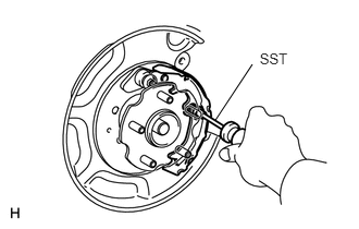
Using SST, install the shoe, pin, compression spring and shoe hold down spring cups.
- SST
- 09718-00011
46540
5.INSTALL NO. 1 PARKING BRAKE SHOE ASSEMBLY LH
Apply high temperature grease to the contact surface of the shoe to anchor pin.
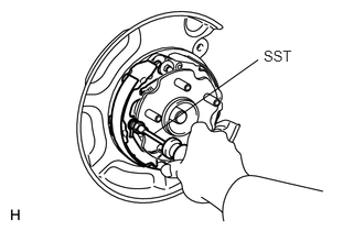
Using SST, install the shoe, pin, compression spring and shoe hold down spring cups.
- SST
- 09718-00011
47406A
6.INSTALL PARKING BRAKE SHOE ADJUSTING SCREW SET
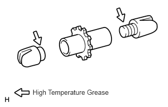
Apply high temperature grease to the adjusting bolt.
Install the screw set.
46550E
7.INSTALL PARKING BRAKE SHOE RETURN TENSION SPRING (for Lower Side)
Using needle-nose pliers, install the tension spring.
47613D
8.INSTALL PARKING BRAKE SHOE STRUT COMPRESSION SPRING
Install the compression spring to the strut.
47614
9.INSTALL PARKING BRAKE SHOE STRUT LH
Install the strut.
46550A
10.INSTALL PARKING BRAKE SHOE RETURN TENSION SPRING (for Upper Side)
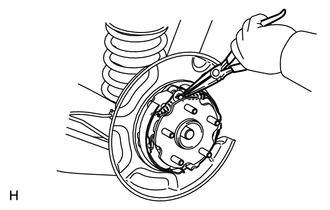
Using needle-nose pliers, install the 2 shoe return tension springs as follows.
- NOTICE:
-
The tension spring (front side) must be installed first, and then the tension spring (rear side) is installed.
Install the tension spring (front side) to fix the No. 1 parking brake shoe in place.
Install the tension spring (rear side) to fix the No. 2 parking brake shoe in place.
11.CHECK PARKING BRAKE INSTALLATION
Check that each part is installed properly.
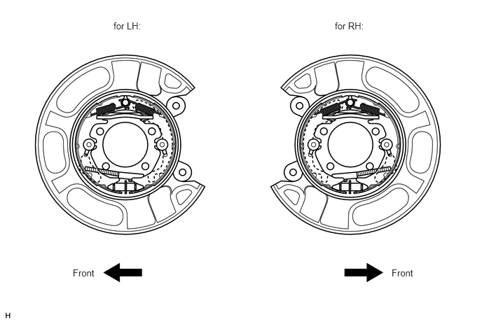
- NOTICE:
-
There should be no oil or grease adhering to the friction surface of the shoe lining and disc.
42431
12.INSTALL REAR DISC
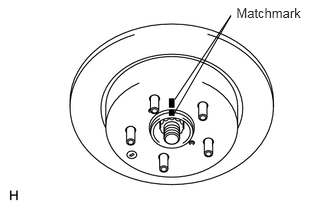
Align the matchmarks and install the disc.
- HINT:
-
When replacing the disc with a new one, select the installation position where the disc has the minimum runout.
13.ADJUST PARKING BRAKE SHOE CLEARANCE
Temporarily install the hub nuts.
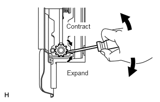
Remove the shoe adjusting hole plug, and then turn the adjuster to expand the shoe adjuster until the disc locks.
Turn and contract the shoe adjuster until the disc can rotate smoothly.
- Standard return notch:
8 notches
Check that the shoe has no brake drag.
Remove the hub nuts.
42491
14.INSTALL PARKING BRAKE SHOE ADJUSTING HOLE PLUG
Install the shoe adjusting hole plug to the rear disc.
15.CONNECT REAR DISC BRAKE CALIPER ASSEMBLY LH
16.INSTALL REAR WHEEL
T = 103 N*m{ 1,050 kgf*cm 76 ft.*lbf }
17.DRIVE VEHICLE
Push the parking brake pedal with a force of 147 N (15 kgf, 33 lbf).
Drive the vehicle at approximately 50 km/h (31 mph) for approximately 400 m (0.25 miles).
- NOTICE:
-
Drive the vehicle on a safe, level and dry road.
Repeat the above steps 2 or 3 times.
18.CHECK AND ADJUST PARKING BRAKE PEDAL TRAVEL
Check and adjust the parking brake pedal travel (see page Brake>PARKING BRAKE>PARKING BRAKE SYSTEM>ADJUSTMENT).