Home › Vehicle Interior › SUPPLEMENTAL RESTRAINT SYSTEMS › AIRBAG SYSTEM › 2013.04–2016.05
RM24M0E _58 Vehicle Interior _059562 SUPPLEMENTAL RESTRAINT SYSTEMS _0291898 AIRBAG SYSTEM C

SUPPLEMENTAL RESTRAINT SYSTEMS  AIRBAG SYSTEM  B1642/81  Lost Communication with Driver Side Satellite Sensor Bus  


DESCRIPTION

When the center airbag sensor receives signals from the lateral deceleration sensor, it determines whether or not the SRS should be activated.

DTC B1642/81 is set when a malfunction is detected in the side airbag sensor LH/RH (for front side) circuit.

DTC No. DTC Detection Condition Trouble Area
B1642/81 When one of following conditions is met:
·

Center airbag sensor detects line short signal, open signal, short to ground signal or short to B+ signal in side airbag sensor LH/RH (for front side) circuit for 2 seconds.

·

Side airbag sensor LH/RH (for rear side) malfunction

·

Center airbag sensor malfunction


·

Floor wire (for LHD)

·

Floor No. 2 wire (for RHD)

·

Door wire LH (for LHD)

·

Door wire RH (for RHD)

·

Side airbag sensor LH/RH (for front side)

·

Rear airbag sensor LH/RH

·

Side airbag sensor LH/RH (for rear side)

·

Center floor airbag sensor

·

Rear floor airbag sensor

·

Center airbag sensor


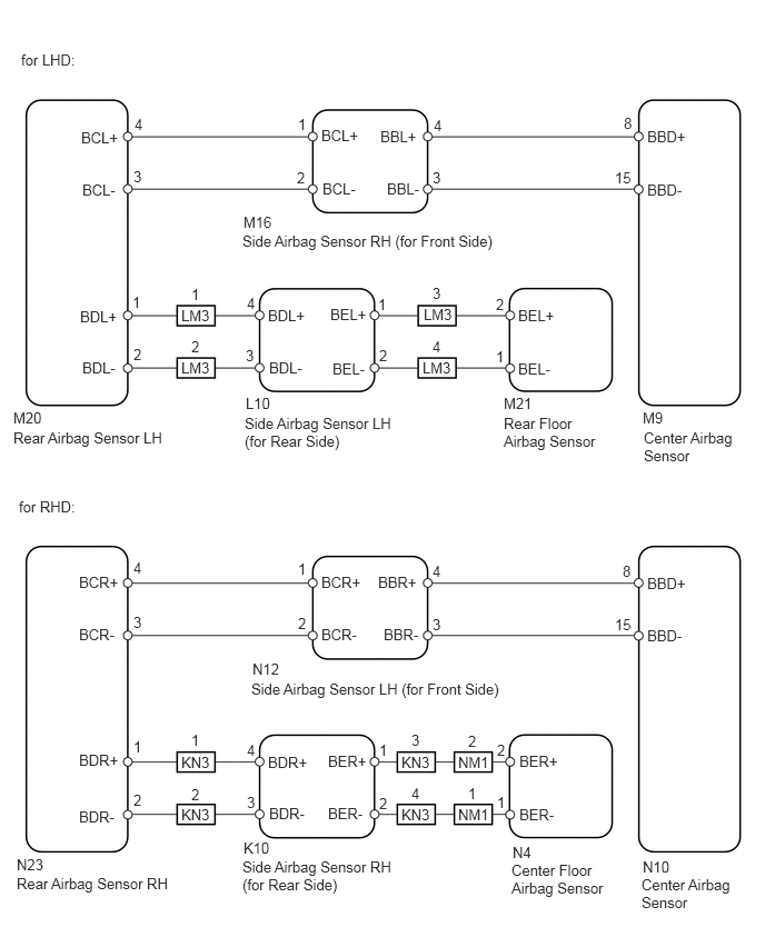
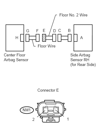
WIRING DIAGRAM

C140726E05
0.198,0.479 0.958,0.729 0.76,0.25 10 false for LHD: 0.177,4.667 0.875,4.885 0.698,0.219 10 false for RHD: 0.125,4.021 1.531,4.198 1.406,0.177 10 false Rear Airbag Sensor LH 2.292,3.885 3.771,4.281 1.479,0.396 10 false Side Airbag Sensor LH (for Rear Side) 4.719,3.885 5.698,4.469 0.979,0.583 10 false Rear Floor Airbag Sensor 6.031,4.021 6.969,4.438 0.938,0.417 10 false Center Airbag Sensor 0.76,1.208 1.188,1.396 0.427,0.188 10 false BCL+ 3.01,1.188 3.448,1.385 0.438,0.198 10 false BCL+ 0.771,1.698 1.167,1.917 0.396,0.219 10 false BCL- 3.021,1.688 3.438,1.917 0.417,0.229 10 false BCL- 0.75,2.885 1.208,3.115 0.458,0.229 10 false BDL+ 2.51,2.875 2.948,3.083 0.438,0.208 10 false BDL+ 1.698,2.875 2.01,3.083 0.313,0.208 10 false LM3 0.771,3.365 1.208,3.583 0.438,0.219 10 false BDL- 2.521,3.365 3.01,3.583 0.49,0.219 10 false BDL- 3.563,1.198 3.99,1.396 0.427,0.198 10 false BBL+ 3.625,1.688 3.99,1.885 0.365,0.198 10 false BBL- 3.094,2.865 3.521,3.083 0.427,0.219 10 false BEL+ 4.854,2.875 5.323,3.063 0.469,0.188 10 false BEL+ 3.115,3.375 3.521,3.552 0.406,0.177 10 false BEL- 4.854,3.375 5.219,3.552 0.365,0.177 10 false BEL- 6.063,1.198 6.51,1.375 0.448,0.177 10 false BBD+ 5.844,1.073 6.031,1.281 0.188,0.208 10 false 8 5.76,1.583 5.979,1.792 0.219,0.208 10 false 15 4.063,1.094 4.25,1.302 0.188,0.208 10 false 4 4.052,1.583 4.271,1.792 0.219,0.208 10 false 3 1.26,1.083 1.448,1.292 0.188,0.208 10 false 4 1.25,1.573 1.469,1.781 0.219,0.208 10 false 3 1.24,2.75 1.427,2.958 0.188,0.208 10 false 1 1.792,2.677 1.979,2.885 0.188,0.208 10 false 1 1.698,3.365 2.01,3.573 0.313,0.208 10 false LM3 1.792,3.167 1.979,3.375 0.188,0.208 10 false 2 3.969,2.865 4.281,3.073 0.313,0.208 10 false LM3 4.052,2.667 4.24,2.875 0.188,0.208 10 false 3 3.958,3.365 4.271,3.573 0.313,0.208 10 false LM3 4.052,3.167 4.24,3.375 0.188,0.208 10 false 4 1.698,7.063 2.01,7.271 0.313,0.208 10 false KN3 1.792,6.854 1.979,7.063 0.188,0.208 10 false 1 1.698,7.552 2.01,7.76 0.313,0.208 10 false KN3 1.792,7.365 1.979,7.573 0.188,0.208 10 false 2 3.76,7.063 4.073,7.271 0.313,0.208 10 false KN3 3.854,6.854 4.042,7.063 0.188,0.208 10 false 3 3.76,7.552 4.073,7.76 0.313,0.208 10 false KN3 3.854,7.354 4.042,7.563 0.188,0.208 10 false 4 4.292,7.063 4.604,7.271 0.313,0.208 10 false NM1 4.385,6.865 4.573,7.073 0.188,0.208 10 false 2 4.292,7.552 4.604,7.76 0.313,0.208 10 false NM1 4.385,7.354 4.573,7.563 0.188,0.208 10 false 1 1.25,3.24 1.469,3.448 0.219,0.208 10 false 2 3.542,2.771 3.729,2.979 0.188,0.208 10 false 1 3.552,3.25 3.771,3.458 0.219,0.208 10 false 2 4.646,2.771 4.833,2.979 0.188,0.208 10 false 2 4.646,3.26 4.865,3.469 0.219,0.208 10 false 1 2.313,2.76 2.5,2.969 0.188,0.208 10 false 4 2.302,3.25 2.521,3.458 0.219,0.208 10 false 3 2.792,1.083 2.979,1.292 0.188,0.208 10 false 1 2.781,1.583 3,1.792 0.219,0.208 10 false 2 6.063,1.698 6.479,1.875 0.417,0.177 10 false BBD- 2.271,2.177 4.656,2.354 2.385,0.177 10 false Side Airbag Sensor RH (for Front Side) 0.156,8.198 1.688,8.438 1.531,0.24 10 false Rear Airbag Sensor RH 2.271,8.042 3.781,8.406 1.51,0.365 10 false Side Airbag Sensor RH (for Rear Side) 4.792,8.073 5.75,8.438 0.958,0.365 10 false Center Floor Airbag Sensor 6.01,8.208 6.885,8.573 0.875,0.365 10 false Center Airbag Sensor 0.74,5.375 1.167,5.563 0.427,0.188 10 false BCR+ 3.01,5.375 3.448,5.573 0.438,0.198 10 false BCR+ 0.74,5.865 1.135,6.083 0.396,0.219 10 false BCR- 3.01,5.865 3.427,6.094 0.417,0.229 10 false BCR- 0.74,7.042 1.198,7.271 0.458,0.229 10 false BDR+ 2.51,7.063 2.948,7.271 0.438,0.208 10 false BDR+ 0.74,7.573 1.177,7.792 0.438,0.219 10 false BDR- 2.521,7.542 3.01,7.76 0.49,0.219 10 false BDR- 3.542,5.375 3.969,5.573 0.427,0.198 10 false BBR+ 3.594,5.865 3.958,6.063 0.365,0.198 10 false BBR- 3.073,7.052 3.5,7.271 0.427,0.219 10 false BER+ 4.865,7.052 5.333,7.24 0.469,0.188 10 false BER+ 3.073,7.542 3.479,7.719 0.406,0.177 10 false BER- 4.865,7.552 5.229,7.729 0.365,0.177 10 false BER- 6.063,5.385 6.51,5.563 0.448,0.177 10 false BBD+ 5.833,5.271 6.021,5.479 0.188,0.208 10 false 8 5.76,5.771 5.979,5.979 0.219,0.208 10 false 15 4.052,5.271 4.24,5.479 0.188,0.208 10 false 4 4.052,5.771 4.271,5.979 0.219,0.208 10 false 3 1.25,5.24 1.438,5.448 0.188,0.208 10 false 4 1.25,5.75 1.469,5.958 0.219,0.208 10 false 3 1.25,6.917 1.438,7.125 0.188,0.208 10 false 1 1.25,7.417 1.469,7.625 0.219,0.208 10 false 2 3.552,6.948 3.74,7.156 0.188,0.208 10 false 1 3.552,7.448 3.771,7.656 0.219,0.208 10 false 2 4.656,6.948 4.844,7.156 0.188,0.208 10 false 2 4.656,7.438 4.875,7.646 0.219,0.208 10 false 1 2.313,6.948 2.5,7.156 0.188,0.208 10 false 4 2.313,7.438 2.531,7.646 0.219,0.208 10 false 3 2.792,5.25 2.979,5.458 0.188,0.208 10 false 1 2.792,5.76 3.01,5.969 0.219,0.208 10 false 2 6.063,5.875 6.479,6.052 0.417,0.177 10 false BBD- 2.354,6.375 4.781,6.594 2.427,0.219 10 false Side Airbag Sensor LH (for Front Side) 0.125,3.833 0.583,4.031 0.458,0.198 10 false M20 2.302,3.698 2.76,3.896 0.458,0.198 10 false L10 4.719,3.698 5.177,3.896 0.458,0.198 10 false M21 6.021,3.833 6.333,4.031 0.313,0.198 10 false M9 2.281,2 2.74,2.198 0.458,0.198 10 false M16 2.365,6.188 2.823,6.385 0.458,0.198 10 false N12 6.021,8.042 6.479,8.24 0.458,0.198 10 false N10 4.802,7.906 5.115,8.104 0.313,0.198 10 false N4 2.281,7.865 2.74,8.063 0.458,0.198 10 false K10 0.156,8.021 0.615,8.219 0.458,0.198 10 false N23

PROCEDURE

1.CHECK STEERING
Result:
Result Proceed to
Steering is LHD side A
Steering is RHD side B


A

2.CHECK FOR PAST DTC

B

32.CHECK FOR PAST DTC
2.CHECK FOR PAST DTC
a.

Turn the ignition switch on (IG), and wait for at least 60 seconds.


c.

Turn the ignition switch off.


d.

Turn the ignition switch on (IG), and wait for at least 60 seconds.


e.

Check the DTCs (see page Vehicle Interior>SUPPLEMENTAL RESTRAINT SYSTEMS>AIRBAG SYSTEM>DTC CHECK / CLEAR).

Result:
Result Proceed to
DTC B1643/81 is output A
DTC B1648/82 is output B

HINT:

DTCs other than DTC B1643/81 and B1648/82 may be output at this time, but they are not related to this check.


A

3.CHECK CONNECTION OF CONNECTOR

B

Go to DTC B1647/82

3.CHECK CONNECTION OF CONNECTOR
a.

Turn the ignition switch off.


b.

Disconnect the cable from the negative (-) battery terminal, and wait for at least 90 seconds.


c.

Check that the connectors are properly connected to the center airbag sensor, rear airbag sensor LH, side airbag sensor LH (for front side), side airbag sensor LH (for rear side), and rear floor airbag sensor.

OK:

Connectors are properly connected.


OK

4.CHECK FLOOR WIRE (OPEN)

NG

CONNECT CONNECTOR

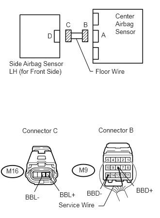
4.CHECK FLOOR WIRE (OPEN)
U189122E02
1.635,0.823 1.938,1.531 1.938,1.531 2,1.531 false 2.448,3.979 2.229,4.417 2.229,4.417 2.115,4.417 false 0.74,4.115 0.927,3.74 false 1.271,4.094 1.021,3.74 false 2.156,4.052 2.313,3.76 false 2.875,3.99 2.552,3.594 false 2.479,0.26 2.979,0.781 0.5,0.521 10 false Center Airbag Sensor 2.177,0.667 2.302,0.833 0.125,0.167 10 false A 1.021,0.688 1.146,0.854 0.125,0.167 10 false D 1.792,0.448 1.917,0.615 0.125,0.167 10 false B 1.417,0.448 1.542,0.615 0.125,0.167 10 false C 0.198,1.281 1.469,1.615 1.271,0.333 10 false Side Airbag Sensor LH (for Front Side) 2.115,2.708 2.958,2.875 0.844,0.167 10 false Connector B 0.479,2.719 1.323,2.885 0.844,0.167 10 false Connector C 2.052,1.448 2.854,1.615 0.802,0.167 10 false Floor Wire 1.26,4.313 2.104,4.458 0.844,0.146 10 false Service Wire 0.135,3.583 0.458,3.74 0.323,0.156 10 false M16 1.698,3.563 1.927,3.719 0.229,0.156 10 false M9 0.542,4.146 0.896,4.323 0.354,0.177 10 false BBL- 1.281,4.094 1.688,4.271 0.406,0.177 10 false BBL+ 2.927,4 3.333,4.156 0.406,0.156 10 false BBD+ 1.865,4.063 2.271,4.219 0.406,0.156 10 false BBD-

a.

Disconnect the connectors from the center airbag sensor and the side airbag sensor LH (for front side).


b.

Using a service wire, connect terminals M9-8 (BBD+) and M9-15 (BBD-) of connector B.

NOTICE:

Do not forcibly insert a service wire into the terminals of the connector when connecting them.


c.

Measure the resistance of the wire harness side connector.

Standard resistance:
Tester Connection Specified Condition
M16-3 (BBL-) - M16-4 (BBL+) Below 1 Ω


OK

5.CHECK FLOOR WIRE (SHORT)

NG

REPAIR OR REPLACE FLOOR WIRE

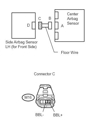
5.CHECK FLOOR WIRE (SHORT)
U189127E02
1.646,0.969 1.958,1.875 1.958,1.875 2.094,1.875 false 1.552,4.021 1.677,3.646 false 1.969,4.021 1.771,3.646 false 2.427,0.417 2.948,0.938 0.521,0.521 10 false Center Airbag Sensor 0.198,1.427 1.438,1.813 1.24,0.385 10 false Side Airbag Sensor LH (for Front Side) 2.208,0.844 2.333,0.99 0.125,0.146 10 false A 1.76,0.573 1.885,0.719 0.125,0.146 10 false B 1.385,0.583 1.51,0.729 0.125,0.146 10 false C 0.979,0.823 1.104,0.969 0.125,0.146 10 false D 2.208,1.802 3.042,1.979 0.833,0.177 10 false Floor Wire 1.229,2.573 2.094,2.76 0.865,0.188 10 false Connector C 0.885,3.417 1.177,3.583 0.292,0.167 10 false M16 1.281,4.042 1.667,4.208 0.385,0.167 10 false BBL- 1.927,4.052 2.51,4.219 0.583,0.167 10 false BBL+

a.

Disconnect the service wire from connector B.


b.

Measure the resistance of the wire harness side connector.

Standard resistance:
Tester Connection Specified Condition
M16-3 (BBL-) - M16-4 (BBL+) 1 MΩ or higher


OK

6.CHECK FLOOR WIRE (TO B+)

NG

REPAIR OR REPLACE FLOOR WIRE

6.CHECK FLOOR WIRE (TO B+)
U189127E02
1.646,0.969 1.958,1.875 1.958,1.875 2.094,1.875 false 1.552,4.021 1.677,3.646 false 1.969,4.021 1.771,3.646 false 2.427,0.417 2.948,0.938 0.521,0.521 10 false Center Airbag Sensor 0.198,1.427 1.438,1.813 1.24,0.385 10 false Side Airbag Sensor LH (for Front Side) 2.208,0.844 2.333,0.99 0.125,0.146 10 false A 1.76,0.573 1.885,0.719 0.125,0.146 10 false B 1.385,0.583 1.51,0.729 0.125,0.146 10 false C 0.979,0.823 1.104,0.969 0.125,0.146 10 false D 2.208,1.802 3.042,1.979 0.833,0.177 10 false Floor Wire 1.229,2.573 2.094,2.76 0.865,0.188 10 false Connector C 0.885,3.417 1.177,3.583 0.292,0.167 10 false M16 1.281,4.042 1.667,4.208 0.385,0.167 10 false BBL- 1.927,4.052 2.51,4.219 0.583,0.167 10 false BBL+

a.

Connect the cable to the negative (-) battery terminal, and wait for at least 2 seconds.


b.

Turn the ignition switch on (IG).


c.

Measure the voltage of the wire harness side connector.

Standard voltage:
Tester Connection Specified Condition
M16-3 (BBL-) - Body ground Below 1 V
M16-4 (BBL+) - Body ground


OK

7.CHECK FLOOR WIRE (TO GROUND)

NG

REPAIR OR REPLACE FLOOR WIRE

7.CHECK FLOOR WIRE (TO GROUND)
U189127E02
1.646,0.969 1.958,1.875 1.958,1.875 2.094,1.875 false 1.552,4.021 1.677,3.646 false 1.969,4.021 1.771,3.646 false 2.427,0.417 2.948,0.938 0.521,0.521 10 false Center Airbag Sensor 0.198,1.427 1.438,1.813 1.24,0.385 10 false Side Airbag Sensor LH (for Front Side) 2.208,0.844 2.333,0.99 0.125,0.146 10 false A 1.76,0.573 1.885,0.719 0.125,0.146 10 false B 1.385,0.583 1.51,0.729 0.125,0.146 10 false C 0.979,0.823 1.104,0.969 0.125,0.146 10 false D 2.208,1.802 3.042,1.979 0.833,0.177 10 false Floor Wire 1.229,2.573 2.094,2.76 0.865,0.188 10 false Connector C 0.885,3.417 1.177,3.583 0.292,0.167 10 false M16 1.281,4.042 1.667,4.208 0.385,0.167 10 false BBL- 1.927,4.052 2.51,4.219 0.583,0.167 10 false BBL+

a.

Turn the ignition switch off.


b.

Disconnect the cable from the negative (-) battery terminal, and wait for at least 90 seconds.


c.

Measure the resistance of the wire harness side connector.

Standard resistance:
Tester Connection Specified Condition
M16-3 (BBL-) - Body ground 1 MΩ or higher
M16-4 (BBL+) - Body ground


OK

8.CHECK FLOOR WIRE (OPEN)

NG

REPAIR OR REPLACE FLOOR WIRE

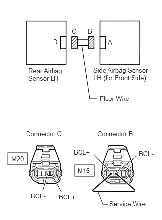
8.CHECK FLOOR WIRE (OPEN)
C364217E03
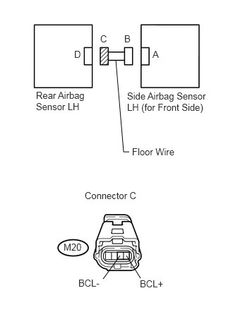
0.167,3.25 0.583,3.5 0.417,0.25 1.583,3.5 2,3.75 0.417,0.25 2.063,2.104 1.906,2.104 1.906,2.104 1.74,0.958 false 0.906,4.052 1.01,3.688 true 1.302,4.073 1.094,3.688 true 2.354,3.667 1.99,3.281 true 2.469,3.656 2.906,3.313 true 2.281,4.344 2.177,4.344 2.177,4.344 2.073,4.063 false 1.125,0.802 1.438,1 0.313,0.198 10 false D 1.521,0.583 1.833,0.781 0.313,0.198 10 false C 1.865,0.583 2.177,0.781 0.313,0.198 10 false B 2.292,0.813 2.604,1.01 0.313,0.198 10 false A 1.979,1.406 3.198,1.854 1.219,0.448 10 false Side Airbag Sensor LH (for Front Side) 0.604,1.417 1.344,1.833 0.74,0.417 10 false Rear Airbag Sensor LH 2.115,2.01 3.271,2.323 1.156,0.313 10 false Floor Wire 0.552,2.76 1.594,3.063 1.042,0.302 10 false Connector C 0.24,3.292 0.552,3.49 0.313,0.198 10 false M20 2.323,4.25 3.177,4.49 0.854,0.24 10 false Service Wire 2.063,2.76 3.104,3.063 1.042,0.302 10 false Connector B 1.646,3.542 1.958,3.74 0.313,0.198 10 false M16 0.656,4.083 1.094,4.302 0.438,0.219 10 false BCL- 1.25,4.104 1.688,4.323 0.438,0.219 10 false BCL+ 2.948,3.188 3.385,3.406 0.438,0.219 10 false BCL- 1.563,3.156 2,3.375 0.438,0.219 10 false BCL+

a.

Disconnect the connectors from the side airbag sensor LH (for front side) and the rear airbag sensor LH.


b.

Using a service wire, connect terminals M16-1 (BCL+) and M16-2 (BCL-) of connector B.

NOTICE:

Do not forcibly insert a service wire into the terminals of the connector when connecting them.


c.

Measure the resistance of the wire harness side connector.

Standard resistance:
Tester Connection Specified Condition
M20-3 (BCL-) - M20-4 (BCL+) Below 1 Ω


OK

9.CHECK FLOOR WIRE (SHORT)

NG

REPAIR OR REPLACE FLOOR WIRE

9.CHECK FLOOR WIRE (SHORT)
U189147E02
1.729,3.719 1.906,3.823 0.177,0.104 1.906,2.24 1.823,2.24 1.823,2.24 1.708,0.885 false 1.521,4.115 1.771,3.771 false 2.073,4.104 1.865,3.771 false 1.875,1.333 3.104,1.667 1.229,0.333 10 false Side Airbag Sensor LH (for Front Side) 0.531,1.323 1.302,1.667 0.771,0.344 10 false Rear Airbag Sensor LH 2.25,0.719 2.375,0.875 0.125,0.156 10 false A 1.833,0.49 1.958,0.646 0.125,0.156 10 false B 1.479,0.49 1.604,0.646 0.125,0.156 10 false C 1.094,0.719 1.219,0.875 0.125,0.156 10 false D 1.25,2.802 2.104,2.969 0.854,0.167 10 false Connector C 1.948,2.156 2.667,2.323 0.719,0.167 10 false Floor Wire 0.938,3.563 1.24,3.708 0.302,0.146 10 false M20 1.156,4.094 1.656,4.25 0.5,0.156 10 false BCL- 2.063,4.104 2.615,4.26 0.552,0.156 10 false BCL+

a.

Disconnect the service wire from connector B.


b.

Measure the resistance of the wire harness side connector.

Standard resistance:
Tester Connection Specified Condition
M20-3 (BCL-) - M20-4 (BCL+) 1 MΩ or higher


OK

10.CHECK FLOOR WIRE (TO B+)

NG

REPAIR OR REPLACE FLOOR WIRE

10.CHECK FLOOR WIRE (TO B+)
U189147E02
1.729,3.719 1.906,3.823 0.177,0.104 1.906,2.24 1.823,2.24 1.823,2.24 1.708,0.885 false 1.521,4.115 1.771,3.771 false 2.073,4.104 1.865,3.771 false 1.875,1.333 3.104,1.667 1.229,0.333 10 false Side Airbag Sensor LH (for Front Side) 0.531,1.323 1.302,1.667 0.771,0.344 10 false Rear Airbag Sensor LH 2.25,0.719 2.375,0.875 0.125,0.156 10 false A 1.833,0.49 1.958,0.646 0.125,0.156 10 false B 1.479,0.49 1.604,0.646 0.125,0.156 10 false C 1.094,0.719 1.219,0.875 0.125,0.156 10 false D 1.25,2.802 2.104,2.969 0.854,0.167 10 false Connector C 1.948,2.156 2.667,2.323 0.719,0.167 10 false Floor Wire 0.938,3.563 1.24,3.708 0.302,0.146 10 false M20 1.156,4.094 1.656,4.25 0.5,0.156 10 false BCL- 2.063,4.104 2.615,4.26 0.552,0.156 10 false BCL+

a.

Connect the cable to the negative (-) battery terminal, and wait for at least 2 seconds.


b.

Turn the ignition switch on (IG).


c.

Measure the voltage of the wire harness side connector.

Standard voltage:
Tester Connection Specified Condition
M20-3 (BCL-) - Body ground Below 1 V
M20-4 (BCL+) - Body ground


OK

11.CHECK FLOOR WIRE (TO GROUND)

NG

REPAIR OR REPLACE FLOOR WIRE

11.CHECK FLOOR WIRE (TO GROUND)
U189147E02
1.729,3.719 1.906,3.823 0.177,0.104 1.906,2.24 1.823,2.24 1.823,2.24 1.708,0.885 false 1.521,4.115 1.771,3.771 false 2.073,4.104 1.865,3.771 false 1.875,1.333 3.104,1.667 1.229,0.333 10 false Side Airbag Sensor LH (for Front Side) 0.531,1.323 1.302,1.667 0.771,0.344 10 false Rear Airbag Sensor LH 2.25,0.719 2.375,0.875 0.125,0.156 10 false A 1.833,0.49 1.958,0.646 0.125,0.156 10 false B 1.479,0.49 1.604,0.646 0.125,0.156 10 false C 1.094,0.719 1.219,0.875 0.125,0.156 10 false D 1.25,2.802 2.104,2.969 0.854,0.167 10 false Connector C 1.948,2.156 2.667,2.323 0.719,0.167 10 false Floor Wire 0.938,3.563 1.24,3.708 0.302,0.146 10 false M20 1.156,4.094 1.656,4.25 0.5,0.156 10 false BCL- 2.063,4.104 2.615,4.26 0.552,0.156 10 false BCL+

a.

Turn the ignition switch off.


b.

Disconnect the cable from the negative (-) battery terminal, and wait for at least 90 seconds.


c.

Measure the resistance of the wire harness side connector.

Standard resistance:
Tester Connection Specified Condition
M20-3 (BCL-) - Body ground 1 MΩ or higher
M20-4 (BCL+) - Body ground


OK

12.CHECK WIRE HARNESS (OPEN)

NG

REPAIR OR REPLACE FLOOR WIRE

12.CHECK WIRE HARNESS (OPEN)
C364218E03
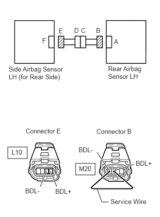
0.167,3.167 0.583,3.417 0.417,0.25 1.625,3.521 2.042,3.771 0.417,0.25 0.865,4.021 1,3.688 true 1.219,4.021 1.083,3.688 true 2.344,3.677 2.083,3.281 true 2.458,3.677 2.875,3.542 true 2.333,4.354 2.188,4.354 2.188,4.354 2.083,4.063 false 0.906,0.792 1.219,0.99 0.313,0.198 10 false F 1.26,0.583 1.573,0.781 0.313,0.198 10 false E 1.594,0.573 1.906,0.771 0.313,0.198 10 false D 1.74,0.573 2.052,0.771 0.313,0.198 10 false C 2.063,0.573 2.375,0.771 0.313,0.198 10 false B 2.448,0.813 2.76,1.01 0.313,0.198 10 false A 2.323,1.396 3.073,1.854 0.75,0.458 10 false Rear Airbag Sensor LH 0.188,1.406 1.396,1.875 1.208,0.469 10 false Side Airbag Sensor LH (for Rear Side) 0.552,2.74 1.531,2.99 0.979,0.25 10 false Connector E 0.25,3.198 0.563,3.396 0.313,0.198 10 false L10 1.688,3.146 2.146,3.385 0.458,0.24 10 false BDL- 1.188,4.042 1.688,4.281 0.5,0.24 10 false BDL+ 1.698,3.552 2.01,3.75 0.313,0.198 10 false M20 2.375,4.26 3.229,4.469 0.854,0.208 10 false Service Wire 2.073,2.75 3.052,3 0.979,0.25 10 false Connector B 0.542,4.031 1.042,4.271 0.5,0.24 10 false BDL- 2.917,3.438 3.375,3.677 0.458,0.24 10 false BDL+

a.

Disconnect the connectors from the rear airbag sensor LH and the side airbag sensor LH (for rear side).


b.

Using a service wire, connect terminals M20-1 (BDL+) and M20-2 (BDL-) of connector B.

NOTICE:

Do not forcibly insert a service wire into the terminals of the connector when connecting them.


c.

Measure the resistance of the wire harness side connector.

Standard resistance:
Tester Connection Specified Condition
L10-3 (BDL-) - L10-4 (BDL+) Below 1 Ω


OK

13.CHECK WIRE HARNESS (SHORT)

NG

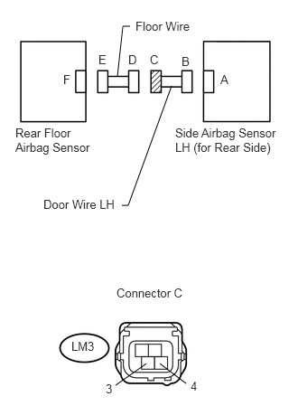
24.CHECK DOOR WIRE (OPEN)
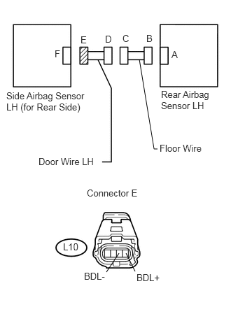
13.CHECK WIRE HARNESS (SHORT)
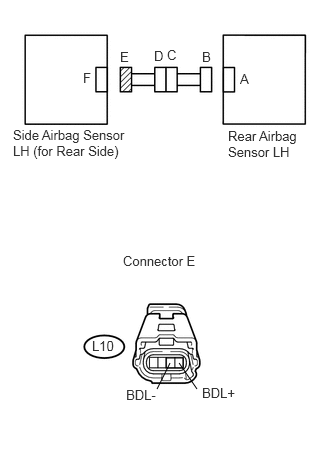
U189159E02
1.729,3.729 1.906,3.833 0.177,0.104 1.635,4.052 1.771,3.781 false 2.052,4.052 1.865,3.781 false 2.375,1.333 3.167,1.719 0.792,0.385 10 false Rear Airbag Sensor LH 0.135,1.323 1.406,1.708 1.271,0.385 10 false Side Airbag Sensor LH (for Rear Side) 2.5,0.74 2.625,0.896 0.125,0.156 10 false A 2.104,0.51 2.229,0.667 0.125,0.156 10 false B 1.74,0.49 1.865,0.646 0.125,0.156 10 false C 1.604,0.5 1.729,0.656 0.125,0.156 10 false D 1.25,0.51 1.375,0.667 0.125,0.156 10 false E 0.865,0.729 0.99,0.885 0.125,0.156 10 false F 1.281,2.635 2.115,2.813 0.833,0.177 10 false Connector E 1.313,4.031 1.802,4.208 0.49,0.177 10 false BDL- 2.104,4.01 2.646,4.188 0.542,0.177 10 false BDL+ 0.958,3.521 1.229,3.698 0.271,0.177 10 false L10

a.

Disconnect the service wire from connector B.


b.

Measure the resistance of the wire harness side connector.

Standard resistance:
Tester Connection Specified Condition
L10-3 (BDL-) - L10-4 (BDL+) 1 MΩ or higher


OK

14.CHECK WIRE HARNESS (TO B+)

NG

25.CHECK DOOR WIRE (SHORT)
14.CHECK WIRE HARNESS (TO B+)
U189159E02
1.729,3.729 1.906,3.833 0.177,0.104 1.635,4.052 1.771,3.781 false 2.052,4.052 1.865,3.781 false 2.375,1.333 3.167,1.719 0.792,0.385 10 false Rear Airbag Sensor LH 0.135,1.323 1.406,1.708 1.271,0.385 10 false Side Airbag Sensor LH (for Rear Side) 2.5,0.74 2.625,0.896 0.125,0.156 10 false A 2.104,0.51 2.229,0.667 0.125,0.156 10 false B 1.74,0.49 1.865,0.646 0.125,0.156 10 false C 1.604,0.5 1.729,0.656 0.125,0.156 10 false D 1.25,0.51 1.375,0.667 0.125,0.156 10 false E 0.865,0.729 0.99,0.885 0.125,0.156 10 false F 1.281,2.635 2.115,2.813 0.833,0.177 10 false Connector E 1.313,4.031 1.802,4.208 0.49,0.177 10 false BDL- 2.104,4.01 2.646,4.188 0.542,0.177 10 false BDL+ 0.958,3.521 1.229,3.698 0.271,0.177 10 false L10

a.

Connect the cable to the negative (-) battery terminal, and wait for at least 2 seconds.


b.

Turn the ignition switch on (IG).


c.

Measure the voltage of the wire harness side connector.

Standard voltage:
Tester Connection Specified Condition
L10-3 (BDL-) - Body ground Below 1 V
L10-4 (BDL+) - Body ground


OK

15.CHECK WIRE HARNESS (TO GROUND)

NG

26.CHECK DOOR WIRE (TO B+)
15.CHECK WIRE HARNESS (TO GROUND)
U189159E02
1.729,3.729 1.906,3.833 0.177,0.104 1.635,4.052 1.771,3.781 false 2.052,4.052 1.865,3.781 false 2.375,1.333 3.167,1.719 0.792,0.385 10 false Rear Airbag Sensor LH 0.135,1.323 1.406,1.708 1.271,0.385 10 false Side Airbag Sensor LH (for Rear Side) 2.5,0.74 2.625,0.896 0.125,0.156 10 false A 2.104,0.51 2.229,0.667 0.125,0.156 10 false B 1.74,0.49 1.865,0.646 0.125,0.156 10 false C 1.604,0.5 1.729,0.656 0.125,0.156 10 false D 1.25,0.51 1.375,0.667 0.125,0.156 10 false E 0.865,0.729 0.99,0.885 0.125,0.156 10 false F 1.281,2.635 2.115,2.813 0.833,0.177 10 false Connector E 1.313,4.031 1.802,4.208 0.49,0.177 10 false BDL- 2.104,4.01 2.646,4.188 0.542,0.177 10 false BDL+ 0.958,3.521 1.229,3.698 0.271,0.177 10 false L10

a.

Turn the ignition switch off.


b.

Disconnect the cable from the negative (-) battery terminal, and wait for at least 90 seconds.


c.

Measure the resistance of the wire harness side connector.

Standard resistance:
Tester Connection Specified Condition
L10-3 (BDL-) - Body ground 1 MΩ or higher
L10-4 (BDL+) - Body ground


OK

16.CHECK WIRE HARNESS (OPEN)

NG

27.CHECK DOOR WIRE (TO GROUND)
16.CHECK WIRE HARNESS (OPEN)
U189365E02
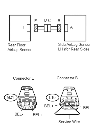
0.917,3.698 0.75,3.969 false 1,3.708 1.188,3.979 false 2.344,3.698 1.979,3.771 false 2.448,3.698 2.896,3.792 false 2.5,4.073 2.5,4.25 false 0.271,1.521 1.198,1.885 0.927,0.365 10 false Rear Floor Airbag Sensor 2.51,0.885 2.781,1.094 0.271,0.208 10 false A 2.063,0.656 2.385,0.854 0.323,0.198 10 false B 1.719,0.646 1.927,0.844 0.208,0.198 10 false C 1.583,0.635 1.781,0.833 0.198,0.198 10 false D 1.229,0.656 1.635,0.854 0.406,0.198 10 false E 0.813,0.885 1.01,1.115 0.198,0.229 10 false F 0.469,2.708 1.406,2.854 0.938,0.146 10 false Connector E 2.031,2.698 2.906,2.99 0.875,0.292 10 false Connector B 2.094,4.26 2.969,4.469 0.875,0.208 10 false Service Wire 0.521,3.99 0.979,4.177 0.458,0.188 10 false BEL- 2.979,3.76 3.323,3.948 0.344,0.188 10 false BEL- 1.177,4.01 1.594,4.25 0.417,0.24 10 false BEL+ 1.583,3.698 2,3.938 0.417,0.24 10 false BEL+ 0.24,3.385 0.604,3.625 0.365,0.24 10 false M21 1.76,3.396 2.073,3.594 0.313,0.198 10 false L10 2.083,1.5 3.292,1.969 1.208,0.469 10 false Side Airbag Sensor LH (for Rear Side)

a.

Disconnect the connectors from the side airbag sensor (for rear side) and the rear floor airbag sensor.


b.

Using a service wire, connect terminals L10-1 (BEL+) and L10-2 (BEL-) of connector B.

NOTICE:

Do not forcibly insert a service wire into the terminals of the connector when connecting them.


c.

Measure the resistance of the wire harness side connector.

Standard resistance:
Tester Connection Specified Condition
M21-1 (BEL-) - M21-2 (BEL+) Below 1 Ω


OK

17.CHECK WIRE HARNESS (SHORT)

NG

28.CHECK DOOR WIRE (OPEN)
17.CHECK WIRE HARNESS (SHORT)
U186116E02
1.646,4.01 1.51,4.365 false 1.75,4.021 1.948,4.375 false 0.188,1.406 1.104,1.865 0.917,0.458 10 false Rear Floor Airbag Sensor 1.865,1.406 3.354,1.792 1.49,0.385 10 false Side Airbag Sensor LH (for Rear Side) 0.771,0.792 1.01,1.052 0.24,0.26 10 false F 1.198,0.573 1.396,0.75 0.198,0.177 10 false E 2.469,0.802 2.667,1 0.198,0.198 10 false A 2.021,0.563 2.313,0.792 0.292,0.229 10 false B 1.698,0.573 1.938,0.833 0.24,0.26 10 false C 1.552,0.573 1.792,0.813 0.24,0.24 10 false D 1.26,3.01 2.177,3.219 0.917,0.208 10 false Connector E 1.292,4.406 1.656,4.583 0.365,0.177 10 false BEL- 1.885,4.406 2.26,4.573 0.375,0.167 10 false BEL+ 0.927,3.75 1.24,3.927 0.313,0.177 10 false M21

a.

Disconnect the service wire from connector B.


b.

Measure the resistance of the wire harness side connector.

Standard resistance:
Tester Connection Specified Condition
M21-1 (BEL-) - M21-2 (BEL+) 1 MΩ or higher


OK

18.CHECK WIRE HARNESS (TO B+)

NG

29.CHECK DOOR WIRE (SHORT)
18.CHECK WIRE HARNESS (TO B+)
U186116E02
1.646,4.01 1.51,4.365 false 1.75,4.021 1.948,4.375 false 0.188,1.406 1.104,1.865 0.917,0.458 10 false Rear Floor Airbag Sensor 1.865,1.406 3.354,1.792 1.49,0.385 10 false Side Airbag Sensor LH (for Rear Side) 0.771,0.792 1.01,1.052 0.24,0.26 10 false F 1.198,0.573 1.396,0.75 0.198,0.177 10 false E 2.469,0.802 2.667,1 0.198,0.198 10 false A 2.021,0.563 2.313,0.792 0.292,0.229 10 false B 1.698,0.573 1.938,0.833 0.24,0.26 10 false C 1.552,0.573 1.792,0.813 0.24,0.24 10 false D 1.26,3.01 2.177,3.219 0.917,0.208 10 false Connector E 1.292,4.406 1.656,4.583 0.365,0.177 10 false BEL- 1.885,4.406 2.26,4.573 0.375,0.167 10 false BEL+ 0.927,3.75 1.24,3.927 0.313,0.177 10 false M21

a.

Connect the cable to the negative (-) battery terminal, and wait for at least 2 seconds.


b.

Turn the ignition switch on (IG).


c.

Measure the voltage of the wire harness side connector.

Standard voltage:
Tester Connection Specified Condition
M21-1 (BEL-) - Body ground Below 1 V
M21-2 (BEL+) - Body ground


OK

19.CHECK WIRE HARNESS (TO GROUND)

NG

30.CHECK DOOR WIRE (TO B+)
19.CHECK WIRE HARNESS (TO GROUND)
U186116E02
1.646,4.01 1.51,4.365 false 1.75,4.021 1.948,4.375 false 0.188,1.406 1.104,1.865 0.917,0.458 10 false Rear Floor Airbag Sensor 1.865,1.406 3.354,1.792 1.49,0.385 10 false Side Airbag Sensor LH (for Rear Side) 0.771,0.792 1.01,1.052 0.24,0.26 10 false F 1.198,0.573 1.396,0.75 0.198,0.177 10 false E 2.469,0.802 2.667,1 0.198,0.198 10 false A 2.021,0.563 2.313,0.792 0.292,0.229 10 false B 1.698,0.573 1.938,0.833 0.24,0.26 10 false C 1.552,0.573 1.792,0.813 0.24,0.24 10 false D 1.26,3.01 2.177,3.219 0.917,0.208 10 false Connector E 1.292,4.406 1.656,4.583 0.365,0.177 10 false BEL- 1.885,4.406 2.26,4.573 0.375,0.167 10 false BEL+ 0.927,3.75 1.24,3.927 0.313,0.177 10 false M21

a.

Turn the ignition switch off.


b.

Disconnect the cable from the negative (-) battery terminal, and wait for at least 90 seconds.


c.

Measure the resistance of the wire harness side connector.

Standard resistance:
Tester Connection Specified Condition
M21-1 (BEL-) - Body ground 1 MΩ or higher
M21-2 (BEL+) - Body ground


OK

20.CHECK SIDE AIRBAG SENSOR ASSEMBLY LH (for Front Side)

NG

31.CHECK DOOR WIRE (TO GROUND)
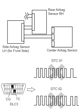
20.CHECK SIDE AIRBAG SENSOR ASSEMBLY LH (for Front Side)
C135371E14
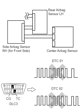
0.354,4.073 0.521,3.656 true 0.719,4.063 0.615,3.854 true 1.99,2.021 3.354,2.198 1.365,0.177 10 false Center Airbag Sensor 0.104,1.875 1.375,2.25 1.271,0.375 10 false Side Airbag Sensor RH (for Front Side) 2.052,0.323 2.854,0.833 0.802,0.51 10 false Rear Airbag Sensor LH 2.135,3.688 2.635,3.854 0.5,0.167 10 false DTC 82 2.167,2.49 2.667,2.656 0.5,0.167 10 false DTC 81 0.396,4.292 0.792,4.448 0.396,0.156 10 false DLC3 0.24,4.094 0.49,4.24 0.25,0.146 10 false CG 0.667,4.094 0.917,4.24 0.25,0.146 10 false TC

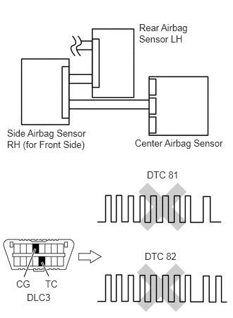
a.

Connect the connectors to the center airbag sensor.


b.

Interchange the side airbag sensor LH (for front side) with the side airbag sensor RH (for front side) and connect the connectors to them.


c.

Connect the cable to the negative (-) battery terminal, and wait for at least 2 seconds.


d.

Turn the ignition switch on (IG), and wait for at least 60 seconds.


f.

Turn the ignition switch off.


g.

Turn the ignition switch on (IG), and wait for at least 60 seconds.


h.

Check for DTCs (see page Vehicle Interior>SUPPLEMENTAL RESTRAINT SYSTEMS>AIRBAG SYSTEM>DTC CHECK / CLEAR).

Result:
Result Proceed to
DTC B1642/81 and B1647/82 are not output A
DTC B1642/81 is output B
DTC B1647/82 is output C

HINT:

DTCs other than DTC B1642/81 and B1647/82 may be output at this time, but they are not related to this check.


A

21.CHECK REAR AIRBAG SENSOR LH

B

REPLACE CENTER AIRBAG SENSOR ASSEMBLY

C

REPLACE SIDE AIRBAG SENSOR ASSEMBLY LH (for Front Side)

21.CHECK REAR AIRBAG SENSOR LH
C135371E15
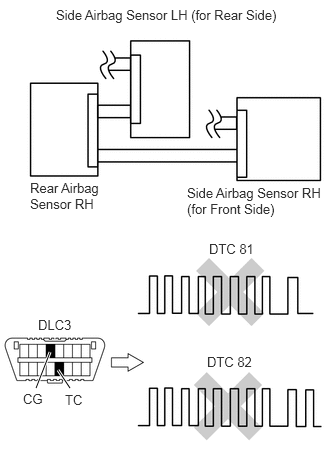
0.385,4.115 0.531,3.667 true 0.74,4.115 0.615,3.854 true 2.177,2.469 2.698,2.615 0.521,0.146 10 false DTC 81 2.146,3.656 2.667,3.802 0.521,0.146 10 false DTC 82 0.281,4.135 0.521,4.292 0.24,0.156 10 false CG 0.688,4.135 0.927,4.292 0.24,0.156 10 false TC 1.948,2.031 3.333,2.208 1.385,0.177 10 false Center Airbag Sensor 0.125,1.885 1.375,2.281 1.25,0.396 10 false Side Airbag Sensor LH (for Front Side) 2.031,0.333 2.813,0.729 0.781,0.396 10 false Rear Airbag Sensor RH 0.406,3.313 0.823,3.469 0.417,0.156 10 false DLC3

a.

Turn the ignition switch off.


b.

Disconnect the cable from the negative (-) battery terminal, and wait for at least 90 seconds.


c.

Interchange the rear airbag sensor LH with the rear airbag sensor RH and connect the connectors to them.


d.

Connect the cable to the negative (-) battery terminal, and wait for at least 2 seconds.


e.

Turn the ignition switch on (IG), and wait for at least 60 seconds.


g.

Turn the ignition switch off.


h.

Turn the ignition switch on (IG), and wait for at least 60 seconds.


i.

Check the DTCs (see page Vehicle Interior>SUPPLEMENTAL RESTRAINT SYSTEMS>AIRBAG SYSTEM>DTC CHECK / CLEAR).

Result:
Result Proceed to
DTC B1642/81 and B1647/82 are not output A
DTC B1642/81 is output B
DTC B1647/82 is output C

HINT:

DTCs other than DTC B1642/81 and B1647/82 may be output at this time, but they are not related to this check.


A

22.CHECK SIDE AIRBAG SENSOR LH (for Rear Side)

B

REPLACE CENTER AIRBAG SENSOR ASSEMBLY

C

REPLACE REAR AIRBAG SENSOR LH

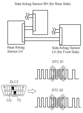
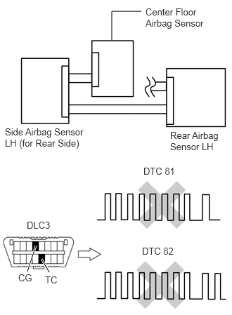
22.CHECK SIDE AIRBAG SENSOR LH (for Rear Side)
C135375E12
0.375,4.042 0.521,3.667 true 0.74,4.042 0.604,3.854 true 2.167,2.469 2.688,2.646 0.521,0.177 10 false DTC 81 2.146,3.646 2.667,3.823 0.521,0.177 10 false DTC 82 0.406,3.302 0.813,3.479 0.406,0.177 10 false DLC3 0.271,4.063 0.51,4.208 0.24,0.146 10 false CG 0.698,4.063 0.938,4.208 0.24,0.146 10 false TC 2.156,1.896 3.396,2.281 1.24,0.385 10 false Side Airbag Sensor LH (for Front Side) 0.302,1.875 1.135,2.51 0.833,0.635 10 false Rear Airbag Sensor LH 0.604,0.073 3.01,0.292 2.406,0.219 10 false Side Airbag Sensor RH (for Rear Side)

a.

Turn the ignition switch off.


b.

Disconnect the cable from the negative (-) battery terminal, and wait for at least 90 seconds.


c.

Interchange the side airbag sensor LH (for rear side) with the side airbag sensor RH (for rear side) and connect the connectors to them.


d.

Connect the cable to the negative (-) battery terminal, and wait for at least 2 seconds.


e.

Turn the ignition switch on (IG), and wait for at least 60 seconds.


g.

Turn the ignition switch off.


h.

Turn the ignition switch on (IG), and wait for at least 60 seconds.


i.

Check the DTCs (see page Vehicle Interior>SUPPLEMENTAL RESTRAINT SYSTEMS>AIRBAG SYSTEM>DTC CHECK / CLEAR).

Result:
Result Proceed to
DTC B1642/81 and B1647/82 are not output A
DTC B1642/81 is output B
DTC B1647/82 is output C

HINT:

DTCs other than DTC B1642/81 and B1647/82 may be output at this time, but they are not related to this check.


A

23.CHECK REAR FLOOR AIRBAG SENSOR

B

REPLACE CENTER AIRBAG SENSOR ASSEMBLY

C

REPLACE SIDE AIRBAG SENSOR ASSEMBLY LH (for Rear Side)

23.CHECK REAR FLOOR AIRBAG SENSOR
C137091E13
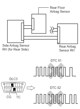
0.406,4.031 0.531,3.646 true 0.729,4.042 0.615,3.844 true 1.656,0.594 1.656,0.167 1.656,0.167 2.094,0.167 false 0.396,3.26 0.802,3.427 0.406,0.167 10 false DLC3 0.271,4.042 0.531,4.229 0.26,0.188 10 false CG 0.667,4.073 0.927,4.26 0.26,0.188 10 false TC 2.125,2.458 2.656,2.635 0.531,0.177 10 false DTC 81 2.104,3.646 2.635,3.823 0.531,0.177 10 false DTC 82 2.521,1.927 3.302,2.302 0.781,0.375 10 false Rear Airbag Sensor LH 0.073,1.875 1.333,2.406 1.26,0.531 10 false Side Airbag Sensor LH (for Rear Side) 2.156,0.094 3.167,0.5 1.01,0.406 10 false Center Floor Airbag Sensor

a.

Turn the ignition switch off.


b.

Disconnect the cable from the negative (-) battery terminal, and wait for at least 90 seconds.


c.

Interchange the rear floor airbag sensor with the center floor airbag sensor and connect the connectors to them.


d.

Connect the cable to the negative (-) battery terminal, and wait for at least 2 seconds.


e.

Turn the ignition switch on (IG), and wait for at least 60 seconds.


g.

Turn the ignition switch off.


h.

Turn the ignition switch on (IG), and wait for at least 60 seconds.


i.

Check the DTCs (see page Vehicle Interior>SUPPLEMENTAL RESTRAINT SYSTEMS>AIRBAG SYSTEM>DTC CHECK / CLEAR).

Result:
Result Proceed to
DTC B1642/81 and B1647/82 are not output A
DTC B1642/81 is output B
DTC B1647/82 is output C

HINT:

DTCs other than DTC B1642/81 and B1647/82 may be output at this time, but they are not related to this check.


A

USE SIMULATION METHOD TO CHECK

B

REPLACE CENTER AIRBAG SENSOR ASSEMBLY

C

REPLACE REAR FLOOR AIRBAG SENSOR

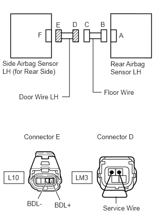
24.CHECK DOOR WIRE (OPEN)
C364219E06
0.083,3.583 0.5,3.833 0.417,0.25 1.5,3.583 1.917,3.833 0.417,0.25 1.292,2.021 1.448,2.021 1.448,2.021 1.448,0.802 false 2.115,1.927 1.938,1.927 1.938,1.927 1.938,0.802 false 0.792,4.146 0.979,3.781 true 1.25,4.177 1.063,3.771 true 2.417,4.25 2.417,4.104 false 0.792,0.646 1.104,0.844 0.313,0.198 10 false F 1.167,0.438 1.479,0.635 0.313,0.198 10 false E 1.51,0.427 1.823,0.625 0.313,0.198 10 false D 1.76,0.427 2.073,0.625 0.313,0.198 10 false C 2.094,0.427 2.406,0.625 0.313,0.198 10 false B 2.479,0.656 2.792,0.854 0.313,0.198 10 false A 2.302,1.25 3.042,1.698 0.74,0.448 10 false Rear Airbag Sensor LH 0.052,1.24 1.26,1.74 1.208,0.5 10 false Side Airbag Sensor LH (for Rear Side) 0.396,1.938 1.333,2.177 0.938,0.24 10 false Door Wire LH 2.167,1.844 3.281,2.104 1.115,0.26 10 false Floor Wire 0.5,2.771 1.563,3.01 1.063,0.24 10 false Connector E 0.167,3.625 0.479,3.823 0.313,0.198 10 false L10 1.573,3.625 1.885,3.823 0.313,0.198 10 false LM3 1.135,4.198 1.635,4.427 0.5,0.229 10 false BDL+ 2.146,4.26 3.094,4.49 0.948,0.229 10 false Service Wire 2.021,2.771 3.083,3.01 1.063,0.24 10 false Connector D 0.563,4.167 1.063,4.396 0.5,0.229 10 false BDL-

a.

Disconnect the door wire connector from the floor wire


b.

Using a service wire, connect terminals LM3-1 and LM3-2 of connector D.

NOTICE:

Do not forcibly insert a service wire into the terminals of the connector when connecting them.


c.

Measure the resistance of the wire harness side connector.

Standard resistance:
Tester Connection Specified Condition
L10-3 (BDL-) - L10-4 (BDL+) Below 1 Ω


OK

REPAIR OR REPLACE FLOOR WIRE

NG

REPAIR OR REPLACE DOOR WIRE LH

25.CHECK DOOR WIRE (SHORT)
U189172E02
1.583,4.052 1.771,3.771 false 2.01,4.042 1.875,3.771 false 2.073,0.885 2.292,2.219 2.292,2.219 2.344,2.219 false 2.552,0.729 2.688,0.875 0.135,0.146 10 false A 2.177,0.49 2.313,0.635 0.135,0.146 10 false B 1.823,0.49 1.958,0.635 0.135,0.146 10 false C 1.563,0.5 1.698,0.646 0.135,0.146 10 false D 1.198,0.51 1.333,0.656 0.135,0.146 10 false E 0.813,0.719 0.948,0.865 0.135,0.146 10 false F 2.396,1.323 3.188,1.688 0.792,0.365 10 false Rear Airbag Sensor LH 0.094,1.344 1.323,1.844 1.229,0.5 10 false Side Airbag Sensor LH (for Rear Side) 1.292,2.792 2.125,2.958 0.833,0.167 10 false Connector E 1.25,4.031 1.75,4.208 0.5,0.177 10 false BDL- 2.031,4.052 2.615,4.229 0.583,0.177 10 false BDL+ 0.938,3.594 1.208,3.74 0.271,0.146 10 false L10 2.375,2.125 3.042,2.302 0.667,0.177 10 false Floor Wire 0.573,2.323 1.49,2.5 0.917,0.177 10 false Door Wire LH

a.

Disconnect the door wire connector from the floor wire.


b.

Measure the resistance of the wire harness side connector.

Standard resistance:
Tester Connection Specified Condition
L10-3 (BDL-) - L10-4 (BDL+) 1 MΩ or higher


OK

REPAIR OR REPLACE FLOOR WIRE

NG

REPAIR OR REPLACE DOOR WIRE LH

26.CHECK DOOR WIRE (TO B+)
U189172E02
1.583,4.052 1.771,3.771 false 2.01,4.042 1.875,3.771 false 2.073,0.885 2.292,2.219 2.292,2.219 2.344,2.219 false 2.552,0.729 2.688,0.875 0.135,0.146 10 false A 2.177,0.49 2.313,0.635 0.135,0.146 10 false B 1.823,0.49 1.958,0.635 0.135,0.146 10 false C 1.563,0.5 1.698,0.646 0.135,0.146 10 false D 1.198,0.51 1.333,0.656 0.135,0.146 10 false E 0.813,0.719 0.948,0.865 0.135,0.146 10 false F 2.396,1.323 3.188,1.688 0.792,0.365 10 false Rear Airbag Sensor LH 0.094,1.344 1.323,1.844 1.229,0.5 10 false Side Airbag Sensor LH (for Rear Side) 1.292,2.792 2.125,2.958 0.833,0.167 10 false Connector E 1.25,4.031 1.75,4.208 0.5,0.177 10 false BDL- 2.031,4.052 2.615,4.229 0.583,0.177 10 false BDL+ 0.938,3.594 1.208,3.74 0.271,0.146 10 false L10 2.375,2.125 3.042,2.302 0.667,0.177 10 false Floor Wire 0.573,2.323 1.49,2.5 0.917,0.177 10 false Door Wire LH

a.

Turn the ignition switch off.


b.

Disconnect the cable from the negative (-) battery terminal, and wait for at least 90 seconds.


c.

Disconnect the door wire connector from the floor wire.


d.

Connect the cable to the negative (-) battery terminal, and wait for at least 2 seconds.


e.

Turn the ignition switch on (IG)


f.

Measure the voltage of the wire harness side connector.

Standard voltage:
Tester Connection Specified Condition
L10-3 (BDL-) - Body ground Below 1 V
L10-4 (BDL+) - Body ground


OK

REPAIR OR REPLACE FLOOR WIRE

NG

REPAIR OR REPLACE DOOR WIRE LH

27.CHECK DOOR WIRE (TO GROUND)
U189172E02
1.583,4.052 1.771,3.771 false 2.01,4.042 1.875,3.771 false 2.073,0.885 2.292,2.219 2.292,2.219 2.344,2.219 false 2.552,0.729 2.688,0.875 0.135,0.146 10 false A 2.177,0.49 2.313,0.635 0.135,0.146 10 false B 1.823,0.49 1.958,0.635 0.135,0.146 10 false C 1.563,0.5 1.698,0.646 0.135,0.146 10 false D 1.198,0.51 1.333,0.656 0.135,0.146 10 false E 0.813,0.719 0.948,0.865 0.135,0.146 10 false F 2.396,1.323 3.188,1.688 0.792,0.365 10 false Rear Airbag Sensor LH 0.094,1.344 1.323,1.844 1.229,0.5 10 false Side Airbag Sensor LH (for Rear Side) 1.292,2.792 2.125,2.958 0.833,0.167 10 false Connector E 1.25,4.031 1.75,4.208 0.5,0.177 10 false BDL- 2.031,4.052 2.615,4.229 0.583,0.177 10 false BDL+ 0.938,3.594 1.208,3.74 0.271,0.146 10 false L10 2.375,2.125 3.042,2.302 0.667,0.177 10 false Floor Wire 0.573,2.323 1.49,2.5 0.917,0.177 10 false Door Wire LH

a.

Disconnect the door wire connector form the floor wire.


b.

Measure the resistance of the wire harness side connector.

Standard resistance:
Tester Connection Specified Condition
L10-3 (BDL-) - Body ground 1 MΩ or higher
L10-4 (BDL+) - Body ground


OK

REPAIR OR REPLACE FLOOR WIRE

NG

REPAIR OR REPLACE DOOR WIRE LH

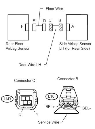
28.CHECK DOOR WIRE (OPEN)
U189367E02
0.833,3.646 1.135,3.792 0.302,0.146 0.917,3.729 0.781,4.052 false 1.073,3.708 1.26,4.063 false 2.333,3.719 2.031,3.885 false 2.469,3.729 2.927,3.885 false 2.448,4.104 2.24,4.427 2.24,4.427 2.208,4.427 false 2.021,1.042 1.667,2.344 1.667,2.344 1.594,2.344 false 1.396,0.927 1.448,0.313 1.448,0.313 1.552,0.313 false 2.583,0.865 2.792,1.073 0.208,0.208 10 false A 2.115,0.656 2.302,0.823 0.188,0.167 10 false B 1.76,0.646 1.958,0.844 0.198,0.198 10 false C 1.563,0.667 1.771,0.833 0.208,0.167 10 false D 1.177,0.667 1.344,0.813 0.167,0.146 10 false E 0.76,0.875 0.99,1.063 0.229,0.188 10 false F 0.208,1.5 1.115,1.906 0.906,0.406 10 false Rear Floor Airbag Sensor 2.146,1.5 3.354,2.094 1.208,0.594 10 false Side Airbag Sensor LH (for Rear Side) 1.656,0.229 2.365,0.458 0.708,0.229 10 false Floor Wire 0.667,2.26 1.594,2.438 0.927,0.177 10 false Door Wire LH 0.51,2.833 1.313,3.021 0.802,0.188 10 false Connector C 2.073,2.771 2.865,2.958 0.792,0.188 10 false Connector B 0.698,4.063 0.854,4.229 0.156,0.167 10 false 3 1.292,4.052 1.469,4.219 0.177,0.167 10 false 4 1.646,3.781 2.021,3.948 0.375,0.167 10 false BEL+ 2.979,3.833 3.323,4.01 0.344,0.177 10 false BEL- 1.375,4.344 2.375,4.51 1,0.167 10 false Service Wire 0.135,3.5 0.5,3.688 0.365,0.188 10 false LM3 1.74,3.406 2.115,3.583 0.375,0.177 10 false L10

a.

Disconnect the door wire connector from the floor wire.


b.

Using a service wire, connect terminals L10-1 (BEL+) and L10-2 (BEL-) of connector B.

NOTICE:

Do not forcibly insert a service wire into the terminals of the connector when connecting them.


c.

Measure the resistance of the wire harness side connector.

Standard resistance:
Tester Connection Specified Condition
LM3-3 - LM3-4 Below 1 Ω


OK

REPAIR OR REPLACE FLOOR WIRE

NG

REPAIR OR REPLACE DOOR WIRE LH

29.CHECK DOOR WIRE (SHORT)
U186117E02
1.688,4.188 1.333,4.438 false 1.844,4.188 2.146,4.417 false 1.5,0.302 1.417,0.302 1.417,0.302 1.354,0.875 false 1.979,0.99 1.479,2.365 1.479,2.365 1.406,2.365 false 0.729,0.833 1.063,1.146 0.333,0.313 10 false F 1.135,0.604 1.323,0.865 0.188,0.26 10 false E 1.479,0.604 1.792,0.917 0.313,0.313 10 false D 1.729,0.604 2.031,0.917 0.302,0.313 10 false C 2.542,0.833 2.854,1.135 0.313,0.302 10 false A 2.094,0.625 2.302,0.979 0.208,0.354 10 false B 1.219,4.396 1.406,4.563 0.188,0.167 10 false 3 2.198,4.365 2.323,4.531 0.125,0.167 10 false 4 0.823,3.906 1.281,4.198 0.458,0.292 10 false LM3 1.344,3.292 2.198,3.469 0.854,0.177 10 false Connector C 0.177,1.448 1.094,1.823 0.917,0.375 10 false Rear Floor Airbag Sensor 2.021,1.448 3.271,1.906 1.25,0.458 10 false Side Airbag Sensor LH (for Rear Side) 1.563,0.219 2.24,0.417 0.677,0.198 10 false Floor Wire 0.5,2.271 1.385,2.458 0.885,0.188 10 false Door Wire LH

a.

Disconnect the door wire connector from the floor wire.


b.

Measure the resistance of the wire harness side connector.

Standard resistance:
Tester Connection Specified Condition
LM3-3 - LM3-4 1 MΩ or higher


OK

REPAIR OR REPLACE FLOOR WIRE

NG

REPAIR OR REPLACE DOOR WIRE LH

30.CHECK DOOR WIRE (TO B+)
U186117E02
1.688,4.188 1.333,4.438 false 1.844,4.188 2.146,4.417 false 1.5,0.302 1.417,0.302 1.417,0.302 1.354,0.875 false 1.979,0.99 1.479,2.365 1.479,2.365 1.406,2.365 false 0.729,0.833 1.063,1.146 0.333,0.313 10 false F 1.135,0.604 1.323,0.865 0.188,0.26 10 false E 1.479,0.604 1.792,0.917 0.313,0.313 10 false D 1.729,0.604 2.031,0.917 0.302,0.313 10 false C 2.542,0.833 2.854,1.135 0.313,0.302 10 false A 2.094,0.625 2.302,0.979 0.208,0.354 10 false B 1.219,4.396 1.406,4.563 0.188,0.167 10 false 3 2.198,4.365 2.323,4.531 0.125,0.167 10 false 4 0.823,3.906 1.281,4.198 0.458,0.292 10 false LM3 1.344,3.292 2.198,3.469 0.854,0.177 10 false Connector C 0.177,1.448 1.094,1.823 0.917,0.375 10 false Rear Floor Airbag Sensor 2.021,1.448 3.271,1.906 1.25,0.458 10 false Side Airbag Sensor LH (for Rear Side) 1.563,0.219 2.24,0.417 0.677,0.198 10 false Floor Wire 0.5,2.271 1.385,2.458 0.885,0.188 10 false Door Wire LH

a.

Turn the ignition switch off.


b.

Disconnect the cable from the negative (-) battery terminal, and wait for at least 90 seconds.


c.

Disconnect the door wire connector from the floor wire.


d.

Connect the cable to the negative (-) battery terminal, and wait for at least 2 seconds.


e.

Turn the ignition switch on (IG).


f.

Measure the voltage of the wire harness side connector.

Standard voltage:
Tester Connection Specified Condition
LM3-3 - Body ground Below 1 V
LM3-4 - Body ground


OK

REPAIR OR REPLACE FLOOR WIRE

NG

REPAIR OR REPLACE DOOR WIRE LH

31.CHECK DOOR WIRE (TO GROUND)
U186117E02
1.688,4.188 1.333,4.438 false 1.844,4.188 2.146,4.417 false 1.5,0.302 1.417,0.302 1.417,0.302 1.354,0.875 false 1.979,0.99 1.479,2.365 1.479,2.365 1.406,2.365 false 0.729,0.833 1.063,1.146 0.333,0.313 10 false F 1.135,0.604 1.323,0.865 0.188,0.26 10 false E 1.479,0.604 1.792,0.917 0.313,0.313 10 false D 1.729,0.604 2.031,0.917 0.302,0.313 10 false C 2.542,0.833 2.854,1.135 0.313,0.302 10 false A 2.094,0.625 2.302,0.979 0.208,0.354 10 false B 1.219,4.396 1.406,4.563 0.188,0.167 10 false 3 2.198,4.365 2.323,4.531 0.125,0.167 10 false 4 0.823,3.906 1.281,4.198 0.458,0.292 10 false LM3 1.344,3.292 2.198,3.469 0.854,0.177 10 false Connector C 0.177,1.448 1.094,1.823 0.917,0.375 10 false Rear Floor Airbag Sensor 2.021,1.448 3.271,1.906 1.25,0.458 10 false Side Airbag Sensor LH (for Rear Side) 1.563,0.219 2.24,0.417 0.677,0.198 10 false Floor Wire 0.5,2.271 1.385,2.458 0.885,0.188 10 false Door Wire LH

a.

Disconnect the door wire connector from the floor wire.


b.

Measure the resistance of the wire harness side connector.

Standard resistance:
Tester Connection Specified Condition
LM3-3 - Body ground 1 MΩ or higher
LM3-4 - Body ground


OK

REPAIR OR REPLACE FLOOR WIRE

NG

REPAIR OR REPLACE DOOR WIRE LH

32.CHECK FOR PAST DTC
a.

Turn the ignition switch on (IG), and wait for at least 60 seconds.


c.

Turn the ignition switch off.


d.

Turn the ignition switch on (IG), and wait for at least 60 seconds.


e.

Check the DTCs (see page Vehicle Interior>SUPPLEMENTAL RESTRAINT SYSTEMS>AIRBAG SYSTEM>DTC CHECK / CLEAR).

Result:
Result Proceed to
DTC B1643/81 is output A
DTC B1648/82 is output B

HINT:

DTCs other than DTC B1643/81 and B1648/82 may be output at this time, but they are not related to this check.


A

33.CHECK CONNECTION OF CONNECTOR

B

Go to DTC B1647/82

33.CHECK CONNECTION OF CONNECTOR
a.

Turn the ignition switch off.


b.

Disconnect the cable from the negative (-) battery terminal, and wait for at least 90 seconds.


c.

Check that the connectors are properly connected to the center airbag sensor, rear airbag sensor RH, side airbag sensor RH (for front side), side airbag sensor RH (for rear side) and center floor airbag sensor.

OK:

Connectors are properly connected.


OK

34.CHECK FLOOR WIRE (OPEN)

NG

CONNECT CONNECTOR

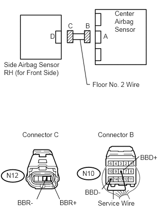
34.CHECK FLOOR WIRE (OPEN)
U189123E02
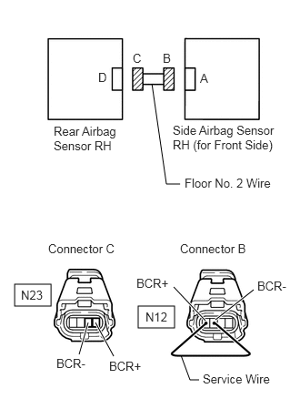
1.677,0.823 1.823,1.771 1.823,1.771 1.885,1.771 false 2.375,3.99 2.375,4.188 false 0.771,4.177 0.969,3.74 false 1.25,4.177 1.052,3.74 false 2.135,3.969 2.313,3.75 false 2.917,3.281 2.594,3.563 false 2.406,0.198 2.906,0.719 0.5,0.521 10 false Center Airbag Sensor 2.167,0.677 2.292,0.844 0.125,0.167 10 false A 1.052,0.677 1.177,0.844 0.125,0.167 10 false D 1.792,0.458 1.917,0.625 0.125,0.167 10 false B 1.427,0.458 1.552,0.625 0.125,0.167 10 false C 0.083,1.271 1.354,1.604 1.271,0.333 10 false Side Airbag Sensor RH (for Front Side) 2.052,2.74 2.896,2.906 0.844,0.167 10 false Connector B 0.469,2.74 1.313,2.906 0.844,0.167 10 false Connector C 1.938,1.688 3.01,1.854 1.073,0.167 10 false Floor No. 2 Wire 2.052,4.177 2.99,4.396 0.938,0.219 10 true Service Wire 0.135,3.594 0.458,3.75 0.323,0.156 10 false N12 1.729,3.552 2.052,3.708 0.323,0.156 10 false N10 0.365,4.167 0.729,4.344 0.365,0.177 10 false BBR- 1.25,4.167 1.667,4.344 0.417,0.177 10 false BBR+ 2.938,3.219 3.344,3.375 0.406,0.156 10 false BBD+ 1.781,3.948 2.146,4.104 0.365,0.156 10 false BBD-

a.

Disconnect the connectors from the center airbag sensor and side airbag sensor RH (for front side).


b.

Using a service wire, connect terminals N10-8 (BBD+) and N10-15 (BBD-) of connector B.

NOTICE:

Do not forcibly insert a service wire into the terminals of the connector when connecting them.


c.

Measure the resistance of the wire harness side connector.

Standard resistance:
Tester Connection Specified Condition
N12-3 (BBR-) - N12-4 (BBR+) Below 1 Ω


OK

35.CHECK FLOOR WIRE (SHORT)

NG

REPAIR OR REPLACE FLOOR NO. 2 WIRE

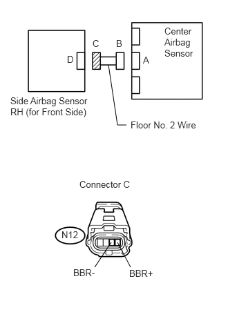
35.CHECK FLOOR WIRE (SHORT)
U189128E02
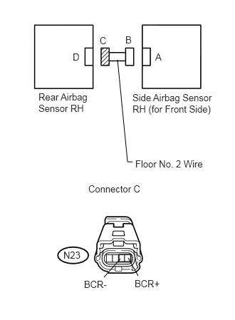
1.635,0.979 1.771,1.885 1.771,1.885 1.906,1.885 false 1.427,4.031 1.677,3.656 false 1.969,4.031 1.771,3.656 false 2.479,0.385 2.969,0.927 0.49,0.542 10 false Center Airbag Sensor 0.156,1.438 1.427,1.875 1.271,0.438 10 false Side Airbag Sensor RH (for Front Side) 2.156,0.823 2.281,0.969 0.125,0.146 10 false A 1.75,0.573 1.875,0.719 0.125,0.146 10 false B 1.396,0.573 1.521,0.719 0.125,0.146 10 false C 1.01,0.813 1.135,0.958 0.125,0.146 10 false D 1.969,1.802 3.135,1.979 1.167,0.177 10 false Floor No. 2 Wire 1.198,2.698 2.063,2.885 0.865,0.188 10 false Connector C 0.927,3.458 1.219,3.625 0.292,0.167 10 false N12 1.104,4.031 1.479,4.198 0.375,0.167 10 false BBR- 1.948,4.042 2.344,4.208 0.396,0.167 10 false BBR+

a.

Disconnect the service wire from the connector B.


b.

Measure the resistance of the wire harness side connector.

Standard resistance:
Tester Connection Specified Condition
N12-3 (BBR-) - N12-4 (BBR+) 1 MΩ or higher


OK

36.CHECK FLOOR WIRE (TO B+)

NG

REPAIR OR REPLACE FLOOR NO. 2 WIRE

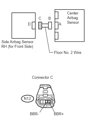
36.CHECK FLOOR WIRE (TO B+)
U189129E02
1.635,0.979 1.792,1.885 1.792,1.885 1.927,1.885 false 1.438,4.042 1.688,3.667 false 1.969,4.031 1.771,3.656 false 2.427,0.385 2.948,0.906 0.521,0.521 10 false Center Airbag Sensor 0.052,1.417 1.323,1.802 1.271,0.385 10 false Side Airbag Sensor RH (for Front Side) 2.125,0.781 2.25,0.927 0.125,0.146 10 false A 1.75,0.573 1.875,0.719 0.125,0.146 10 false B 1.396,0.573 1.521,0.719 0.125,0.146 10 false C 1.01,0.781 1.135,0.927 0.125,0.146 10 false D 1.958,1.802 3.125,1.979 1.167,0.177 10 false Floor No. 2 Wire 1.156,2.698 2.021,2.885 0.865,0.188 10 false Connector C 0.865,3.458 1.156,3.625 0.292,0.167 10 false N12 1.083,4.01 1.469,4.177 0.385,0.167 10 false BBR- 1.948,4.01 2.365,4.177 0.417,0.167 10 false BBR+

a.

Connect the cable to the negative (-) battery terminal, and wait for at least 2 seconds.


b.

Turn the ignition switch on (IG).


c.

Measure the voltage of the wire harness side connector.

Standard voltage:
Tester Connection Specified Condition
N12-3 (BBL-) - Body ground Below 1 V
N12-4 (BBL+) - Body ground


OK

37.CHECK FLOOR WIRE (TO GROUND)

NG

REPAIR OR REPLACE FLOOR NO. 2 WIRE

37.CHECK FLOOR WIRE (TO GROUND)
U189129E02
1.635,0.979 1.792,1.885 1.792,1.885 1.927,1.885 false 1.438,4.042 1.688,3.667 false 1.969,4.031 1.771,3.656 false 2.427,0.385 2.948,0.906 0.521,0.521 10 false Center Airbag Sensor 0.052,1.417 1.323,1.802 1.271,0.385 10 false Side Airbag Sensor RH (for Front Side) 2.125,0.781 2.25,0.927 0.125,0.146 10 false A 1.75,0.573 1.875,0.719 0.125,0.146 10 false B 1.396,0.573 1.521,0.719 0.125,0.146 10 false C 1.01,0.781 1.135,0.927 0.125,0.146 10 false D 1.958,1.802 3.125,1.979 1.167,0.177 10 false Floor No. 2 Wire 1.156,2.698 2.021,2.885 0.865,0.188 10 false Connector C 0.865,3.458 1.156,3.625 0.292,0.167 10 false N12 1.083,4.01 1.469,4.177 0.385,0.167 10 false BBR- 1.948,4.01 2.365,4.177 0.417,0.167 10 false BBR+

a.

Turn the ignition switch off.


b.

Disconnect the cable from the negative (-) battery terminal, and wait for at least 90 seconds.


c.

Measure the resistance of the wire harness side connector.

Standard resistance:
Tester Connection Specified Condition
N12-3 (BBL-) - Body ground 1 MΩ or higher
N12-4 (BBL+) - Body ground


OK

38.CHECK FLOOR WIRE (OPEN)

NG

REPAIR OR REPLACE FLOOR NO. 2 WIRE

38.CHECK FLOOR WIRE (OPEN)
C364217E05
0.167,3.25 0.583,3.5 0.417,0.25 1.583,3.5 2,3.75 0.417,0.25 2.063,2.104 1.906,2.104 1.906,2.104 1.74,0.958 false 0.906,4.052 1.01,3.688 true 1.302,4.073 1.094,3.688 true 2.354,3.667 1.99,3.281 true 2.469,3.656 2.906,3.313 true 2.281,4.344 2.177,4.344 2.177,4.344 2.073,4.063 false 1.125,0.802 1.438,1 0.313,0.198 10 false D 1.521,0.583 1.833,0.781 0.313,0.198 10 false C 1.865,0.583 2.177,0.781 0.313,0.198 10 false B 2.292,0.813 2.604,1.01 0.313,0.198 10 false A 1.979,1.406 3.198,1.854 1.219,0.448 10 false Side Airbag Sensor RH (for Front Side) 0.615,1.417 1.354,1.833 0.74,0.417 10 false Rear Airbag Sensor RH 2.115,2.01 3.271,2.323 1.156,0.313 10 false Floor No. 2 Wire 0.552,2.76 1.594,3.063 1.042,0.302 10 false Connector C 0.24,3.292 0.552,3.49 0.313,0.198 10 false N23 2.323,4.25 3.177,4.49 0.854,0.24 10 false Service Wire 2.063,2.76 3.104,3.063 1.042,0.302 10 false Connector B 1.667,3.542 1.979,3.74 0.313,0.198 10 false N12 0.646,4.073 1.083,4.292 0.438,0.219 10 false BCR- 1.25,4.104 1.688,4.323 0.438,0.219 10 false BCR+ 2.948,3.188 3.385,3.406 0.438,0.219 10 false BCR- 1.563,3.156 2,3.375 0.438,0.219 10 false BCR+

a.

Disconnect the connectors from the side airbag sensor RH (for front side) and rear airbag sensor RH.


b.

Using a service wire, connect terminals N12-1 (BCR+) - and N12-2 (BCR-) of connector B.

NOTICE:

Do not forcibly insert a service wire into the terminals of the connector when connecting them.


c.

Measure the resistance of the wire harness side connector.

Standard resistance:
Tester Connection Specified Condition
N23-3 (BCR-) - N23-4 (BCR+) Below 1 Ω


OK

39.CHECK FLOOR WIRE (SHORT)

NG

REPAIR OR REPLACE FLOOR NO. 2 WIRE

39.CHECK FLOOR WIRE (SHORT)
U189148E02
1.74,3.719 1.917,3.823 0.177,0.104 1.938,2.365 1.865,2.365 1.865,2.365 1.719,0.875 false 1.521,4.052 1.76,3.781 false 2.021,4.031 1.875,3.771 false 1.938,1.344 3.208,1.729 1.271,0.385 10 false Side Airbag Sensor RH (for Front Side) 0.563,1.333 1.344,1.677 0.781,0.344 10 false Rear Airbag Sensor RH 2.271,0.75 2.396,0.906 0.125,0.156 10 false A 1.833,0.5 1.958,0.656 0.125,0.156 10 false B 1.458,0.51 1.583,0.667 0.125,0.156 10 false C 1.063,0.75 1.188,0.906 0.125,0.156 10 false D 1.292,2.677 2.146,2.844 0.854,0.167 10 false Connector C 1.979,2.313 3.021,2.479 1.042,0.167 10 false Floor No. 2 Wire 0.927,3.646 1.229,3.792 0.302,0.146 10 false N23 1.229,4.073 1.635,4.229 0.406,0.156 10 false BCR- 1.969,4.063 2.417,4.219 0.448,0.156 10 false BCR+

a.

Disconnect the service wire from connector B.


b.

Measure the resistance of the wire harness side connector.

Standard resistance:
Tester Connection Specified Condition
N23-3 (BCR-) - N23-4 (BCR+) 1 MΩ or higher


OK

40.CHECK FLOOR WIRE (TO B+)

NG

REPAIR OR REPLACE FLOOR NO. 2 WIRE

40.CHECK FLOOR WIRE (TO B+)
U189148E02
1.74,3.719 1.917,3.823 0.177,0.104 1.938,2.365 1.865,2.365 1.865,2.365 1.719,0.875 false 1.521,4.052 1.76,3.781 false 2.021,4.031 1.875,3.771 false 1.938,1.344 3.208,1.729 1.271,0.385 10 false Side Airbag Sensor RH (for Front Side) 0.563,1.333 1.344,1.677 0.781,0.344 10 false Rear Airbag Sensor RH 2.271,0.75 2.396,0.906 0.125,0.156 10 false A 1.833,0.5 1.958,0.656 0.125,0.156 10 false B 1.458,0.51 1.583,0.667 0.125,0.156 10 false C 1.063,0.75 1.188,0.906 0.125,0.156 10 false D 1.292,2.677 2.146,2.844 0.854,0.167 10 false Connector C 1.979,2.313 3.021,2.479 1.042,0.167 10 false Floor No. 2 Wire 0.927,3.646 1.229,3.792 0.302,0.146 10 false N23 1.229,4.073 1.635,4.229 0.406,0.156 10 false BCR- 1.969,4.063 2.417,4.219 0.448,0.156 10 false BCR+

a.

Connect the cable to the negative (-) battery terminal, and wait for at least 2 seconds.


b.

Turn the ignition switch on (IG).


c.

Measure the voltage of the wire harness side connector.

Standard voltage:
Tester Connection Specified Condition
N23-3 (BCR-) - Body ground Below 1 V
N23-4 (BCR+) - Body ground


OK

41.CHECK FLOOR WIRE (TO GROUND)

NG

REPAIR OR REPLACE FLOOR NO. 2 WIRE

41.CHECK FLOOR WIRE (TO GROUND)
U189148E02
1.74,3.719 1.917,3.823 0.177,0.104 1.938,2.365 1.865,2.365 1.865,2.365 1.719,0.875 false 1.521,4.052 1.76,3.781 false 2.021,4.031 1.875,3.771 false 1.938,1.344 3.208,1.729 1.271,0.385 10 false Side Airbag Sensor RH (for Front Side) 0.563,1.333 1.344,1.677 0.781,0.344 10 false Rear Airbag Sensor RH 2.271,0.75 2.396,0.906 0.125,0.156 10 false A 1.833,0.5 1.958,0.656 0.125,0.156 10 false B 1.458,0.51 1.583,0.667 0.125,0.156 10 false C 1.063,0.75 1.188,0.906 0.125,0.156 10 false D 1.292,2.677 2.146,2.844 0.854,0.167 10 false Connector C 1.979,2.313 3.021,2.479 1.042,0.167 10 false Floor No. 2 Wire 0.927,3.646 1.229,3.792 0.302,0.146 10 false N23 1.229,4.073 1.635,4.229 0.406,0.156 10 false BCR- 1.969,4.063 2.417,4.219 0.448,0.156 10 false BCR+

a.

Turn the ignition switch off.


b.

Disconnect the cable front the negative (-) battery terminal, and wait for at least 90 seconds.


c.

Measure the resistance of the wire harness side connector.

Standard resistance:
Tester Connection Specified Condition
N23-3 (BCR-) - Body ground 1 MΩ or higher
N23-4 (BCR+) - Body ground


OK

42.CHECK WIRE HARNESS (OPEN)

NG

REPAIR OR REPLACE FLOOR NO. 2 WIRE

42.CHECK WIRE HARNESS (OPEN)
C364218E10
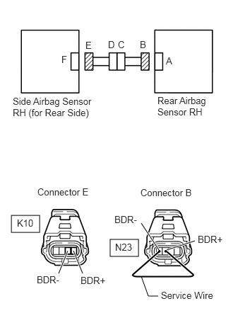
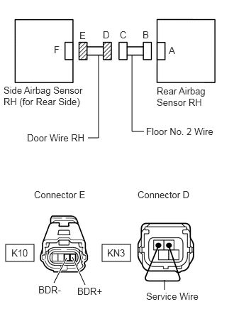
0.167,3.167 0.583,3.417 0.417,0.25 1.625,3.521 2.042,3.771 0.417,0.25 0.865,4.021 1,3.688 true 1.219,4.021 1.083,3.688 true 2.344,3.677 2.083,3.281 true 2.458,3.677 2.875,3.542 true 2.333,4.354 2.188,4.354 2.188,4.354 2.083,4.063 false 0.906,0.792 1.219,0.99 0.313,0.198 10 false F 1.26,0.583 1.573,0.781 0.313,0.198 10 false E 1.594,0.573 1.906,0.771 0.313,0.198 10 false D 1.74,0.573 2.052,0.771 0.313,0.198 10 false C 2.063,0.573 2.375,0.771 0.313,0.198 10 false B 2.448,0.813 2.76,1.01 0.313,0.198 10 false A 2.323,1.396 3.073,1.854 0.75,0.458 10 false Rear Airbag Sensor RH 0.188,1.406 1.396,1.875 1.208,0.469 10 false Side Airbag Sensor RH (for Rear Side) 0.552,2.74 1.531,2.99 0.979,0.25 10 false Connector E 0.25,3.198 0.563,3.396 0.313,0.198 10 false K10 1.688,3.146 2.146,3.385 0.458,0.24 10 false BDR- 1.188,4.042 1.688,4.281 0.5,0.24 10 false BDR+ 1.698,3.552 2.01,3.75 0.313,0.198 10 false N23 2.375,4.26 3.229,4.469 0.854,0.208 10 false Service Wire 2.073,2.75 3.052,3 0.979,0.25 10 false Connector B 0.542,4.031 1.042,4.271 0.5,0.24 10 false BDR- 2.917,3.438 3.375,3.677 0.458,0.24 10 false BDR+

a.

Disconnect the connectors from the rear airbag sensor RH and side airbag sensor RH (for rear side).


b.

Using a service wire, connect terminals N23-1 (BDR+) and N23-2 (BDR-) of connector B.

NOTICE:

Do not forcibly insert a service wire into the terminals of the connector when connecting them.


c.

Measure the resistance of the wire harness side connector.

Standard resistance:
Tester Connection Specified Condition
K10-3 (BDR-) - K10-4 (BDR+) Below 1 Ω


OK

43.CHECK WIRE HARNESS (SHORT)

NG

54.CHECK DOOR WIRE (OPEN)
43.CHECK WIRE HARNESS (SHORT)
U189160E02
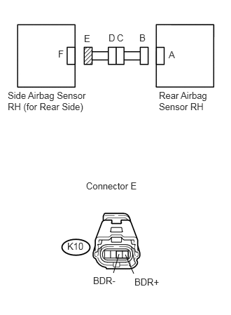
1.729,3.729 1.906,3.833 0.177,0.104 1.688,4.052 1.771,3.771 false 1.99,4.063 1.865,3.781 false 2.365,1.333 3.177,1.719 0.813,0.385 10 false Rear Airbag Sensor RH 0.115,1.333 1.396,1.719 1.281,0.385 10 false Side Airbag Sensor RH (for Rear Side) 2.51,0.729 2.635,0.885 0.125,0.156 10 false A 2.073,0.479 2.198,0.635 0.125,0.156 10 false B 1.74,0.479 1.865,0.635 0.125,0.156 10 false C 1.615,0.479 1.74,0.635 0.125,0.156 10 false D 1.25,0.49 1.375,0.646 0.125,0.156 10 false E 0.865,0.719 0.99,0.875 0.125,0.156 10 false F 1.281,2.677 2.115,2.854 0.833,0.177 10 false Connector E 1.385,4.083 1.781,4.26 0.396,0.177 10 false BDR- 2,4.104 2.417,4.281 0.417,0.177 10 false BDR+ 1,3.573 1.271,3.75 0.271,0.177 10 false K10

a.

Disconnect the service wire from connector B.


b.

Measure the resistance of the wire harness side connector.

Standard resistance:
Tester Connection Specified Condition
K10-3 (BDR-) - K10-4 (BDR+) 1 MΩ or higher


OK

44.CHECK WIRE HARNESS (TO B+)

NG

55.CHECK DOOR WIRE (SHORT)
44.CHECK WIRE HARNESS (TO B+)
U189160E02
1.729,3.729 1.906,3.833 0.177,0.104 1.688,4.052 1.771,3.771 false 1.99,4.063 1.865,3.781 false 2.365,1.333 3.177,1.719 0.813,0.385 10 false Rear Airbag Sensor RH 0.115,1.333 1.396,1.719 1.281,0.385 10 false Side Airbag Sensor RH (for Rear Side) 2.51,0.729 2.635,0.885 0.125,0.156 10 false A 2.073,0.479 2.198,0.635 0.125,0.156 10 false B 1.74,0.479 1.865,0.635 0.125,0.156 10 false C 1.615,0.479 1.74,0.635 0.125,0.156 10 false D 1.25,0.49 1.375,0.646 0.125,0.156 10 false E 0.865,0.719 0.99,0.875 0.125,0.156 10 false F 1.281,2.677 2.115,2.854 0.833,0.177 10 false Connector E 1.385,4.083 1.781,4.26 0.396,0.177 10 false BDR- 2,4.104 2.417,4.281 0.417,0.177 10 false BDR+ 1,3.573 1.271,3.75 0.271,0.177 10 false K10

a.

Connect the cable to the negative (-) battery terminal, and wait for at least 2 seconds.


b.

Turn the ignition switch on (IG).


c.

Measure the voltage of the wire harness side connector.

Standard voltage:
Tester Connection Specified Condition
K10-3 (BDR-) - Body ground Below 1 V
K10-4 (BDR+) - Body ground


OK

45.CHECK WIRE HARNESS (TO GROUND)

NG

56.CHECK DOOR WIRE (TO B+)
45.CHECK WIRE HARNESS (TO GROUND)
U189160E03
1.688,4.063 1.771,3.781 false 2,4.063 1.875,3.781 false 2.344,1.333 3.156,1.719 0.813,0.385 10 false Rear Airbag Sensor RH 0.083,1.427 1.365,1.813 1.281,0.385 10 false Side Airbag Sensor RH (for Rear Side) 2.49,0.771 2.615,0.927 0.125,0.156 10 false A 2.094,0.5 2.219,0.656 0.125,0.156 10 false B 1.74,0.5 1.865,0.656 0.125,0.156 10 false C 1.615,0.5 1.74,0.656 0.125,0.156 10 false D 1.26,0.5 1.385,0.656 0.125,0.156 10 false E 0.802,0.771 0.927,0.927 0.125,0.156 10 false F 1.344,2.802 2.177,2.979 0.833,0.177 10 false Connector E 1.427,4.094 1.823,4.271 0.396,0.177 10 false BDR- 2,4.104 2.417,4.281 0.417,0.177 10 false BDR+ 1,3.594 1.271,3.771 0.271,0.177 10 false K10

a.

Turn the ignition switch off.


b.

Disconnect the cable from the negative (-) battery terminal, and wait for at least 90 seconds.


c.

Measure the resistance of the wire harness side connector.

Standard resistance:
Tester Connection Specified Condition
K10-3 (BDR-) - Body ground 1 MΩ or higher
K10-4 (BDR+) - Body ground


OK

46.CHECK WIRE HARNESS (OPEN)

NG

57.CHECK DOOR WIRE (TO GROUND)
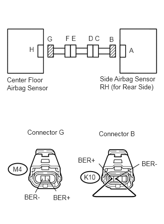
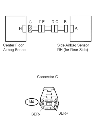
46.CHECK WIRE HARNESS (OPEN)
U189361E02
0.896,3.729 0.74,4.021 false 1,3.729 1.177,3.99 false 2.344,3.729 2.073,3.417 false 2.438,3.719 2.917,3.427 false 0.146,1.583 1.073,1.948 0.927,0.365 10 false Center Floor Airbag Sensor 2.708,0.969 3.031,1.177 0.323,0.208 10 false A 2.292,0.74 2.521,0.979 0.229,0.24 10 false B 1.99,0.719 2.135,0.865 0.146,0.146 10 false C 1.854,0.719 2.01,0.927 0.156,0.208 10 false D 1.5,0.719 1.76,0.927 0.26,0.208 10 false E 1.375,0.719 1.573,0.865 0.198,0.146 10 false F 0.99,0.729 1.167,0.927 0.177,0.198 10 false G 0.615,0.948 0.781,1.135 0.167,0.188 10 false H 0.573,2.677 1.51,2.833 0.938,0.156 10 false Connector G 2.073,2.708 2.938,2.906 0.865,0.198 10 false Connector B 0.271,3.448 0.583,3.656 0.313,0.208 10 false M4 1.76,3.615 2.031,3.76 0.271,0.146 10 false K10 2.969,3.333 3.406,3.594 0.438,0.26 10 false BER- 0.51,4.031 0.896,4.208 0.385,0.177 10 false BER- 1.115,4.042 1.5,4.25 0.385,0.208 10 false BER+ 1.635,3.26 2.021,3.469 0.385,0.208 10 false BER+ 2.094,1.563 3.333,2.229 1.24,0.667 10 false Side Airbag Sensor RH (for Rear Side)

a.

Disconnect the connectors from the side airbag sensor (for rear side) and center airbag sensor.


b.

Using a service wire, connect terminals K10-1 (BER+) and K10-2 (BER-) of connector B.

NOTICE:

Do not forcibly insert a service wire into the terminals of the connector when connecting them.


c.

Measure the resistance of the wire harness side connector.

Standard resistance:
Tester Connection Specified Condition
M4-1 (BER-) - M4-2 (BER+) Below 1 Ω


OK

47.CHECK WIRE HARNESS (SHORT)

NG

58.CHECK DOOR WIRE (OPEN)
47.CHECK WIRE HARNESS (SHORT)
U186103E02
1.458,4.073 1.74,3.792 false 2.094,4.063 1.833,3.792 false 2.74,0.948 2.885,1.104 0.146,0.156 10 false A 2.344,0.708 2.49,0.865 0.146,0.156 10 false B 2.031,0.708 2.177,0.865 0.146,0.156 10 false C 1.885,0.708 2.031,0.865 0.146,0.156 10 false D 1.542,0.708 1.688,0.865 0.146,0.156 10 false E 1.417,0.719 1.563,0.875 0.146,0.156 10 false F 1.052,0.719 1.198,0.875 0.146,0.156 10 false G 0.698,0.958 0.844,1.115 0.146,0.156 10 false H 1.354,2.719 2.198,2.906 0.844,0.188 10 false Connector G 2.094,1.563 3.323,1.969 1.229,0.406 10 false Side Airbag Sensor RH (for Rear Side) 0.115,1.563 1.031,1.99 0.917,0.427 10 false Center Floor Airbag Sensor 1.052,3.635 1.292,3.813 0.24,0.177 10 false M4 1.146,4.083 1.542,4.26 0.396,0.177 10 false BER- 2.135,4.052 2.531,4.229 0.396,0.177 10 false BER+

a.

Disconnect the service wire from the connector B.


b.

Measure the resistance of the wire harness side connector.

Standard resistance:
Tester Connection Specified Condition
M4-1 (BER-) - M4-2 (BER+) 1 MΩ or higher


OK

48.CHECK WIRE HARNESS (TO B+)

NG

59.CHECK DOOR WIRE (SHORT)
48.CHECK WIRE HARNESS (TO B+)
U186103E02
1.458,4.073 1.74,3.792 false 2.094,4.063 1.833,3.792 false 2.74,0.948 2.885,1.104 0.146,0.156 10 false A 2.344,0.708 2.49,0.865 0.146,0.156 10 false B 2.031,0.708 2.177,0.865 0.146,0.156 10 false C 1.885,0.708 2.031,0.865 0.146,0.156 10 false D 1.542,0.708 1.688,0.865 0.146,0.156 10 false E 1.417,0.719 1.563,0.875 0.146,0.156 10 false F 1.052,0.719 1.198,0.875 0.146,0.156 10 false G 0.698,0.958 0.844,1.115 0.146,0.156 10 false H 1.354,2.719 2.198,2.906 0.844,0.188 10 false Connector G 2.094,1.563 3.323,1.969 1.229,0.406 10 false Side Airbag Sensor RH (for Rear Side) 0.115,1.563 1.031,1.99 0.917,0.427 10 false Center Floor Airbag Sensor 1.052,3.635 1.292,3.813 0.24,0.177 10 false M4 1.146,4.083 1.542,4.26 0.396,0.177 10 false BER- 2.135,4.052 2.531,4.229 0.396,0.177 10 false BER+

a.

Connect the cable to the negative (-) battery terminal, and wait for at least 2 seconds.


b.

Turn the ignition switch on (IG).


c.

Measure the voltage of the wire harness side connector.

Standard voltage:
Tester Connection Specified Condition
M4-1 (BER-) - Body ground Below 1 V
M4-2 (BER+) - Body ground


OK

49.CHECK WIRE HARNESS (TO GROUND)

NG

60.CHECK DOOR WIRE (TO B+)
49.CHECK WIRE HARNESS (TO GROUND)
U186103E02
1.458,4.073 1.74,3.792 false 2.094,4.063 1.833,3.792 false 2.74,0.948 2.885,1.104 0.146,0.156 10 false A 2.344,0.708 2.49,0.865 0.146,0.156 10 false B 2.031,0.708 2.177,0.865 0.146,0.156 10 false C 1.885,0.708 2.031,0.865 0.146,0.156 10 false D 1.542,0.708 1.688,0.865 0.146,0.156 10 false E 1.417,0.719 1.563,0.875 0.146,0.156 10 false F 1.052,0.719 1.198,0.875 0.146,0.156 10 false G 0.698,0.958 0.844,1.115 0.146,0.156 10 false H 1.354,2.719 2.198,2.906 0.844,0.188 10 false Connector G 2.094,1.563 3.323,1.969 1.229,0.406 10 false Side Airbag Sensor RH (for Rear Side) 0.115,1.563 1.031,1.99 0.917,0.427 10 false Center Floor Airbag Sensor 1.052,3.635 1.292,3.813 0.24,0.177 10 false M4 1.146,4.083 1.542,4.26 0.396,0.177 10 false BER- 2.135,4.052 2.531,4.229 0.396,0.177 10 false BER+

a.

Turn the ignition switch off.


b.

Disconnect the cable from the negative (-) battery terminal, and wait for at least 90 seconds.


c.

Measure the resistance of the wire harness side connector.

Standard resistance:
Tester Connection Specified Condition
M4-1 (BER-) - Body ground 1 MΩ or higher
M4-2 (BER+) - Body ground


OK

50.CHECK SIDE AIRBAG SENSOR ASSEMBLY RH (for Front Side)

NG

61.CHECK DOOR WIRE (TO GROUND)
50.CHECK SIDE AIRBAG SENSOR ASSEMBLY RH (for Front Side)
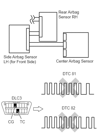
C135371E16
0.354,4.083 0.521,3.667 true 0.708,4.063 0.604,3.854 true 1.99,2.031 3.354,2.208 1.365,0.177 10 false Center Airbag Sensor 0.104,1.885 1.344,2.26 1.24,0.375 10 false Side Airbag Sensor LH (for Front Side) 2.042,0.323 2.896,0.656 0.854,0.333 10 false Rear Airbag Sensor RH 2.156,3.656 2.656,3.823 0.5,0.167 10 false DTC 82 2.188,2.469 2.688,2.635 0.5,0.167 10 false DTC 81 0.417,4.302 0.813,4.458 0.396,0.156 10 false DLC3 0.25,4.094 0.5,4.24 0.25,0.146 10 false CG 0.677,4.083 0.927,4.229 0.25,0.146 10 false TC

a.

Connect the connectors to the center airbag sensor.


b.

Interchange the side airbag sensor RH (for front side) with the side airbag sensor LH (for front side) and connect the connectors to them.


c.

Connect the cable to the negative (-) battery terminal, and wait for at least 2 seconds.


d.

Turn the ignition switch on (IG), and wait for at least 60 seconds.


f.

Turn the ignition switch off.


g.

Turn the ignition switch on (IG), and wait for at least 60 seconds.


h.

Check the DTCs (see page Vehicle Interior>SUPPLEMENTAL RESTRAINT SYSTEMS>AIRBAG SYSTEM>DTC CHECK / CLEAR).

Result:
Result Proceed to
DTC B1642/81 and B1647/82 are not output A
DTC B1642/81 is output B
DTC B1647/82 is output C

HINT:

DTCs other than DTC B1642/81 and B1647/82 may be output at this time, but they are not related to this check.


A

51.CHECK REAR AIRBAG SENSOR RH

B

REPLACE CENTER AIRBAG SENSOR ASSEMBLY

C

REPLACE SIDE AIRBAG SENSOR ASSEMBLY RH (for Front Side)

51.CHECK REAR AIRBAG SENSOR RH
C135371E17
0.365,4.063 0.531,3.646 true 0.719,4.063 0.615,3.854 true 1.958,2.052 3.323,2.229 1.365,0.177 10 false Center Airbag Sensor 0.104,1.885 1.344,2.281 1.24,0.396 10 false Side Airbag Sensor RH (for Front Side) 2.021,0.333 2.854,0.823 0.833,0.49 10 false Rear Airbag Sensor LH 2.156,3.646 2.656,3.813 0.5,0.167 10 false DTC 82 2.177,2.479 2.677,2.646 0.5,0.167 10 false DTC 81 0.396,4.292 0.792,4.448 0.396,0.156 10 false DLC3 0.26,4.073 0.51,4.219 0.25,0.146 10 false CG 0.667,4.073 0.917,4.219 0.25,0.146 10 false TC

a.

Turn the ignition switch off.


b.

Disconnect the cable from the negative (-) battery terminal, and wait for at least 90 seconds.


c.

Interchange the rear airbag sensor RH with the rear airbag sensor LH and connect the connectors to them.


d.

Connect the cable to the negative (-) battery terminal, and wait for at least 2 seconds.


e.

Turn the ignition switch on (IG), and wait for at least 60 seconds.


g.

Turn the ignition switch off.


h.

Turn the ignition switch on (IG), and wait for at least 60 seconds.


i.

Check the DTCs (see page Vehicle Interior>SUPPLEMENTAL RESTRAINT SYSTEMS>AIRBAG SYSTEM>DTC CHECK / CLEAR).

Result:
Result Proceed to
DTC B1642/81 and B1647/82 are not output A
DTC B1642/81 is output B
DTC B1647/82 is output C

HINT:

DTCs other than DTC B1642/81 and B1647/82 may be output at this time, but they are not related to this check.


A

52.CHECK SIDE AIRBAG SENSOR ASSEMBLY RH (for Rear Side)

B

REPLACE CENTER AIRBAG SENSOR ASSEMBLY

C

REPLACE REAR AIRBAG SENSOR RH

52.CHECK SIDE AIRBAG SENSOR ASSEMBLY RH (for Rear Side)
C135375E13
0.375,4.042 0.521,3.667 true 0.729,4.042 0.604,3.854 true 2.177,2.51 2.698,2.688 0.521,0.177 10 false DTC 81 2.156,3.688 2.677,3.865 0.521,0.177 10 false DTC 82 0.396,3.302 0.802,3.479 0.406,0.177 10 false DLC3 0.24,4.073 0.479,4.219 0.24,0.146 10 false CG 0.677,4.083 0.917,4.229 0.24,0.146 10 false TC 1.948,1.927 3.375,2.333 1.427,0.406 10 false Side Airbag Sensor RH (for Front Side) 0.313,1.875 1.146,2.51 0.833,0.635 10 false Rear Airbag Sensor RH 0.583,0.073 3,0.26 2.417,0.188 10 false Side Airbag Sensor LH (for Rear Side)

a.

Turn the ignition switch off.


b.

Disconnect the cable from the negative (-) battery terminal, and wait for at least 90 seconds.


c.

Interchange the side airbag sensor RH (for rear side) with the side airbag sensor LH (for rear side) and connect the connectors to them.


d.

Connect the cable to the negative (-) battery terminal, and wait for at least 2 seconds.


f.

Turn the ignition switch off.


g.

Turn the ignition switch on (IG), and wait for at least 60 seconds.


h.

Check the DTCs (see page Vehicle Interior>SUPPLEMENTAL RESTRAINT SYSTEMS>AIRBAG SYSTEM>DTC CHECK / CLEAR).

Result:
Result Proceed to
DTC B1642/81 and B1647/82 are not output A
DTC B1642/81 is output B
DTC B1647/82 is output C

HINT:

DTCs other than DTC B1642/81 and B1647/82 may be output at this time, but they are not related to this check.


A

53.CHECK CENTER FLOOR AIRBAG SENSOR

B

REPLACE CENTER AIRBAG SENSOR ASSEMBLY

C

REPLACE SIDE AIRBAG SENSOR ASSEMBLY RH (for Rear Side)

53.CHECK CENTER FLOOR AIRBAG SENSOR
C137091E14
0.396,4.063 0.521,3.667 true 0.729,4.063 0.615,3.865 true 1.656,0.604 1.656,0.323 1.656,0.323 2.094,0.323 false 0.406,3.302 0.813,3.469 0.406,0.167 10 false DLC3 0.281,4.073 0.542,4.26 0.26,0.188 10 false CG 0.698,4.083 0.958,4.271 0.26,0.188 10 false TC 2.177,2.51 2.708,2.688 0.531,0.177 10 false DTC 81 2.146,3.677 2.677,3.854 0.531,0.177 10 false DTC 82 2.542,1.906 3.313,2.271 0.771,0.365 10 false Rear Airbag Sensor RH 0.104,1.865 1.365,2.427 1.26,0.563 10 false Side Airbag Sensor RH (for Rear Side) 2.146,0.24 3.167,0.625 1.021,0.385 10 false Rear Floor Airbag Sensor

a.

Turn the ignition switch off.


b.

Disconnect the cable from the negative (-) battery terminal, and wait for at least 90 seconds.


c.

Interchange the center floor airbag sensor with the rear floor airbag sensor and connect the connectors to them.


d.

Connect the cable to the negative (-) battery terminal, and wait for at least 2 seconds.


e.

Turn the ignition switch on (IG), and wait for at least 60 seconds.


g.

Turn the ignition switch off.


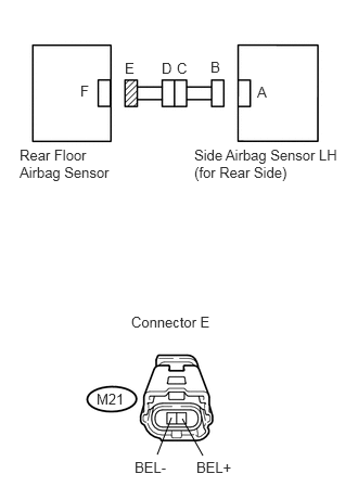
h.

Turn the ignition switch on (IG), and wait for at least 60 seconds.


i.

Check the DTCs (see page Vehicle Interior>SUPPLEMENTAL RESTRAINT SYSTEMS>AIRBAG SYSTEM>DTC CHECK / CLEAR).

Result:
Result Proceed to
DTC B1642/81 and B1647/82 are not output A
DTC B1642/81 is output B
DTC B1647/82 is output C

HINT:

DTCs other than DTC B1642/81 and B1647/82 may be output at this time, but they are not related to this check.


A

USE SIMULATION METHOD TO CHECK

B

REPLACE CENTER AIRBAG SENSOR ASSEMBLY

C

REPLACE CENTER FLOOR AIRBAG SENSOR

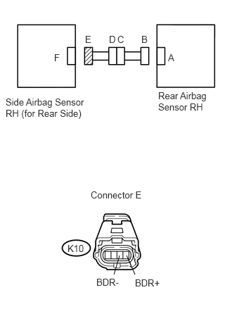
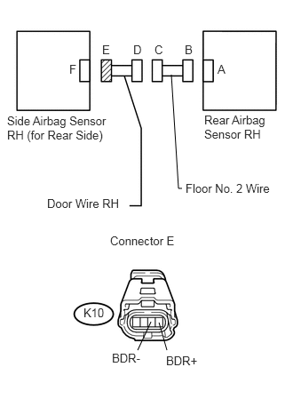
54.CHECK DOOR WIRE (OPEN)
C364219E05
0.083,3.583 0.5,3.833 0.417,0.25 1.5,3.583 1.917,3.833 0.417,0.25 1.292,2.021 1.448,2.021 1.448,2.021 1.448,0.802 false 2.115,1.927 1.938,1.927 1.938,1.927 1.938,0.802 false 0.792,4.146 0.979,3.781 true 1.25,4.177 1.063,3.771 true 2.417,4.25 2.417,4.104 false 0.792,0.646 1.104,0.844 0.313,0.198 10 false F 1.167,0.438 1.479,0.635 0.313,0.198 10 false E 1.51,0.427 1.823,0.625 0.313,0.198 10 false D 1.76,0.427 2.073,0.625 0.313,0.198 10 false C 2.094,0.427 2.406,0.625 0.313,0.198 10 false B 2.479,0.656 2.792,0.854 0.313,0.198 10 false A 2.302,1.25 3.042,1.698 0.74,0.448 10 false Rear Airbag Sensor RH 0.052,1.24 1.26,1.74 1.208,0.5 10 false Side Airbag Sensor RH (for Rear Side) 0.396,1.938 1.333,2.177 0.938,0.24 10 false Door Wire RH 2.146,1.844 3.26,2.104 1.115,0.26 10 false Floor No. 2 Wire 0.5,2.771 1.563,3.01 1.063,0.24 10 false Connector E 0.167,3.625 0.479,3.823 0.313,0.198 10 false K10 1.573,3.625 1.885,3.823 0.313,0.198 10 false KN3 1.135,4.188 1.635,4.417 0.5,0.229 10 false BDR+ 2.146,4.26 3.094,4.49 0.948,0.229 10 false Service Wire 2.021,2.771 3.083,3.01 1.063,0.24 10 false Connector D 0.563,4.167 1.063,4.396 0.5,0.229 10 false BDR-

a.

Disconnect the door wire connector from the floor No. 2 wire.


b.

Using a service wire, connect terminals KN3-1 and KN3-2 of connector D.


c.

Measure the resistance of the wire harness side connector.

Standard resistance:
Tester Connection Specified Condition
K10-3 (BDR-) - K10-4 (BDR+) Below 1 Ω


OK

REPAIR OR REPLACE FLOOR NO. 2 WIRE

NG

REPAIR OR REPLACE DOOR WIRE RH

55.CHECK DOOR WIRE (SHORT)
U189173E02
1.615,4.104 1.771,3.771 false 1.958,4.104 1.865,3.781 false 2.01,0.875 2.094,2.208 2.094,2.208 2.135,2.208 false 2.552,0.729 2.688,0.875 0.135,0.146 10 false A 2.167,0.5 2.302,0.646 0.135,0.146 10 false B 1.813,0.5 1.948,0.646 0.135,0.146 10 false C 1.563,0.5 1.698,0.646 0.135,0.146 10 false D 1.198,0.5 1.333,0.646 0.135,0.146 10 false E 0.813,0.729 0.948,0.875 0.135,0.146 10 false F 2.396,1.323 3.188,1.708 0.792,0.385 10 false Rear Airbag Sensor RH 0.083,1.333 1.354,1.844 1.271,0.51 10 false Side Airbag Sensor RH (for Rear Side) 1.292,2.74 2.125,2.906 0.833,0.167 10 false Connector E 1.313,4.115 1.813,4.292 0.5,0.177 10 false BDR- 1.948,4.146 2.531,4.323 0.583,0.177 10 false BDR+ 0.979,3.583 1.25,3.729 0.271,0.146 10 false K10 2.177,2.125 3.219,2.302 1.042,0.177 10 false Floor No. 2 Wire 0.552,2.302 1.5,2.479 0.948,0.177 10 false Door Wire RH

a.

Disconnect the door wire connector from the floor No. 2 wire.


b.

Measure the resistance of the wire harness side connector.

Standard resistance:
Tester Connection Specified Condition
K10-3 (BDR-) - K10-4 (BDR+) 1 MΩ or higher


OK

REPAIR OR REPLACE FLOOR NO. 2 WIRE

NG

REPAIR OR REPLACE DOOR WIRE RH

56.CHECK DOOR WIRE (TO B+)
U189173E02
1.615,4.104 1.771,3.771 false 1.958,4.104 1.865,3.781 false 2.01,0.875 2.094,2.208 2.094,2.208 2.135,2.208 false 2.552,0.729 2.688,0.875 0.135,0.146 10 false A 2.167,0.5 2.302,0.646 0.135,0.146 10 false B 1.813,0.5 1.948,0.646 0.135,0.146 10 false C 1.563,0.5 1.698,0.646 0.135,0.146 10 false D 1.198,0.5 1.333,0.646 0.135,0.146 10 false E 0.813,0.729 0.948,0.875 0.135,0.146 10 false F 2.396,1.323 3.188,1.708 0.792,0.385 10 false Rear Airbag Sensor RH 0.083,1.333 1.354,1.844 1.271,0.51 10 false Side Airbag Sensor RH (for Rear Side) 1.292,2.74 2.125,2.906 0.833,0.167 10 false Connector E 1.313,4.115 1.813,4.292 0.5,0.177 10 false BDR- 1.948,4.146 2.531,4.323 0.583,0.177 10 false BDR+ 0.979,3.583 1.25,3.729 0.271,0.146 10 false K10 2.177,2.125 3.219,2.302 1.042,0.177 10 false Floor No. 2 Wire 0.552,2.302 1.5,2.479 0.948,0.177 10 false Door Wire RH

a.

Turn the ignition switch off.


b.

Disconnect the cable from the negative (-) battery terminal, and wait for at least 90 seconds.


c.

Disconnect the door wire connector from the floor No. 2 wire.


d.

Connect the cable to the negative (-) battery terminal, and wait for at least 2 seconds.


e.

Turn the ignition switch on (IG).


f.

Measure the voltage of the wire harness side connector.

Standard voltage:
Tester Connection Specified Condition
K10-3 (BDR-) - Body ground Below 1 V
K10-4 (BDR+) - Body ground


OK

REPAIR OR REPLACE FLOOR NO. 2 WIRE

NG

REPAIR OR REPLACE DOOR WIRE RH

57.CHECK DOOR WIRE (TO GROUND)
U189173E02
1.615,4.104 1.771,3.771 false 1.958,4.104 1.865,3.781 false 2.01,0.875 2.094,2.208 2.094,2.208 2.135,2.208 false 2.552,0.729 2.688,0.875 0.135,0.146 10 false A 2.167,0.5 2.302,0.646 0.135,0.146 10 false B 1.813,0.5 1.948,0.646 0.135,0.146 10 false C 1.563,0.5 1.698,0.646 0.135,0.146 10 false D 1.198,0.5 1.333,0.646 0.135,0.146 10 false E 0.813,0.729 0.948,0.875 0.135,0.146 10 false F 2.396,1.323 3.188,1.708 0.792,0.385 10 false Rear Airbag Sensor RH 0.083,1.333 1.354,1.844 1.271,0.51 10 false Side Airbag Sensor RH (for Rear Side) 1.292,2.74 2.125,2.906 0.833,0.167 10 false Connector E 1.313,4.115 1.813,4.292 0.5,0.177 10 false BDR- 1.948,4.146 2.531,4.323 0.583,0.177 10 false BDR+ 0.979,3.583 1.25,3.729 0.271,0.146 10 false K10 2.177,2.125 3.219,2.302 1.042,0.177 10 false Floor No. 2 Wire 0.552,2.302 1.5,2.479 0.948,0.177 10 false Door Wire RH

a.

Disconnect the door wire connector from the floor No. 2 wire.


b.

Measure the resistance of the wire harness side connector.

Standard resistance:
Tester Connection Specified Condition
K10-3 (BDR-) - Body ground 1 MΩ or higher
K10-4 (BDR+) - Body ground


OK

REPAIR OR REPLACE FLOOR NO. 2 WIRE

NG

REPAIR OR REPLACE DOOR WIRE RH

58.CHECK DOOR WIRE (OPEN)
U189354E02
0.833,3.698 1.135,3.844 0.302,0.146 0.906,3.76 0.792,4.083 false 1.052,3.74 1.167,4.063 false 2.333,3.781 1.938,3.969 false 2.438,3.781 2.875,3.948 false 2.323,4.146 2.323,4.302 false 2.219,0.708 1.729,1.063 1.729,1.063 1.729,1.969 false 1.333,0.313 1.594,0.573 0.26,0.26 10 false F 1.458,0.313 1.729,0.521 0.271,0.208 10 false E 2.708,0.563 3,0.74 0.292,0.177 10 false A 2.323,0.323 2.615,0.521 0.292,0.198 10 false B 1.99,0.313 2.229,0.573 0.24,0.26 10 false C 1.792,0.313 1.99,0.542 0.198,0.229 10 false D 0.958,0.323 1.333,0.552 0.375,0.229 10 false G 0.646,0.563 0.771,0.802 0.125,0.24 10 false H 0.094,1.156 0.969,1.771 0.875,0.615 10 false Center Floor Airbag Sensor 1.396,2.021 2.292,2.198 0.896,0.177 10 false Door Wire RH 2.135,1.156 3.354,1.552 1.219,0.396 10 false Side Airbag Sensor RH (for Rear Side) 0.448,2.802 1.313,2.979 0.865,0.177 10 false Connector C 2.083,2.771 2.906,2.979 0.823,0.208 10 false Connector B 2.01,4.333 3.177,4.542 1.167,0.208 10 false Service Wire 1.51,3.875 1.927,4.031 0.417,0.156 10 false BER+ 2.958,3.906 3.323,4.135 0.365,0.229 10 false BER- 1.198,4.094 1.302,4.26 0.104,0.167 10 false 4 0.708,4.094 0.833,4.26 0.125,0.167 10 false 3 0.135,3.531 0.552,3.823 0.417,0.292 10 false KN3 1.781,3.24 2.104,3.563 0.323,0.323 10 false K10

a.

Disconnect the door wire connector from the floor No. 2 wire.


b.

Using a service wire, connect terminals K10-1 (BER+) and K10-2 (BER-) of connector B.

NOTICE:

Do not forcibly insert a service wire into the terminals of the connector when connecting them.


c.

Measure the resistance of the wire harness side connector.

Standard resistance:
Tester Connection Specified Condition
KN3-3 - KN3-4 Below 1 Ω


NG

REPAIR OR REPLACE DOOR WIRE RH

OK

62.CHECK FLOOR NO. 2 WIRE (OPEN)
59.CHECK DOOR WIRE (SHORT)
U186119E02
1.677,3.958 1.583,4.26 false 1.833,3.958 1.938,4.26 false 2.24,0.906 1.781,1.24 1.781,1.24 1.781,2.26 false 1.271,3.177 2.177,3.365 0.906,0.188 10 false Connector C 1.49,4.281 1.667,4.427 0.177,0.146 10 false 3 1.938,4.292 2.125,4.448 0.188,0.156 10 false 4 0.854,3.75 1.188,3.917 0.333,0.167 10 false KN3 0.635,0.76 0.844,0.958 0.208,0.198 10 false H 0.969,0.531 1.219,0.708 0.25,0.177 10 false G 1.323,0.531 1.542,0.719 0.219,0.188 10 false F 1.448,0.531 1.646,0.688 0.198,0.156 10 false E 1.792,0.531 1.99,0.75 0.198,0.219 10 false D 1.979,0.521 2.219,0.677 0.24,0.156 10 false C 2.333,0.531 2.531,0.688 0.198,0.156 10 false B 2.719,0.76 2.865,0.927 0.146,0.167 10 false A 0.146,1.354 1.063,1.865 0.917,0.51 10 false Center Floor Airbag Sensor 1.344,2.313 2.24,2.49 0.896,0.177 10 false Door Wire RH 2.125,1.375 3.365,1.792 1.24,0.417 10 false Side Airbag Sensor RH (for Rear Side)

a.

Disconnect the door wire connector from the floor No. 2 wire.


b.

Measure the resistance of the wire harness side connector.

Standard resistance:
Tester Connection Specified Condition
KN3-3 - KN3-4 1 MΩ or higher


NG

REPAIR OR REPLACE DOOR WIRE RH

OK

63.CHECK FLOOR NO. 2 WIRE (SHORT)
60.CHECK DOOR WIRE (TO B+)
U186119E02
1.677,3.958 1.583,4.26 false 1.833,3.958 1.938,4.26 false 2.24,0.906 1.781,1.24 1.781,1.24 1.781,2.26 false 1.271,3.177 2.177,3.365 0.906,0.188 10 false Connector C 1.49,4.281 1.667,4.427 0.177,0.146 10 false 3 1.938,4.292 2.125,4.448 0.188,0.156 10 false 4 0.854,3.75 1.188,3.917 0.333,0.167 10 false KN3 0.635,0.76 0.844,0.958 0.208,0.198 10 false H 0.969,0.531 1.219,0.708 0.25,0.177 10 false G 1.323,0.531 1.542,0.719 0.219,0.188 10 false F 1.448,0.531 1.646,0.688 0.198,0.156 10 false E 1.792,0.531 1.99,0.75 0.198,0.219 10 false D 1.979,0.521 2.219,0.677 0.24,0.156 10 false C 2.333,0.531 2.531,0.688 0.198,0.156 10 false B 2.719,0.76 2.865,0.927 0.146,0.167 10 false A 0.146,1.354 1.063,1.865 0.917,0.51 10 false Center Floor Airbag Sensor 1.344,2.313 2.24,2.49 0.896,0.177 10 false Door Wire RH 2.125,1.375 3.365,1.792 1.24,0.417 10 false Side Airbag Sensor RH (for Rear Side)

a.

Turn the ignition switch off.


b.

Disconnect the cable from the negative (-) battery terminal, and wait for at least 90 seconds.


c.

Disconnect the door wire connector from the floor No. 2 wire.


d.

Connect the cable to the negative (-) battery terminal, and wait for at least 2 seconds.


e.

Turn the ignition switch on (IG).


f.

Measure the voltage of the wire harness side connector.

Standard voltage:
Tester Connection Specified Condition
KN3-3 - Body ground Below 1 V
KN3-4 - Body ground


NG

REPAIR OR REPLACE DOOR WIRE RH

OK

64.CHECK FLOOR NO. 2 WIRE (TO B+)
61.CHECK DOOR WIRE (TO GROUND)
U186119E02
1.677,3.958 1.583,4.26 false 1.833,3.958 1.938,4.26 false 2.24,0.906 1.781,1.24 1.781,1.24 1.781,2.26 false 1.271,3.177 2.177,3.365 0.906,0.188 10 false Connector C 1.49,4.281 1.667,4.427 0.177,0.146 10 false 3 1.938,4.292 2.125,4.448 0.188,0.156 10 false 4 0.854,3.75 1.188,3.917 0.333,0.167 10 false KN3 0.635,0.76 0.844,0.958 0.208,0.198 10 false H 0.969,0.531 1.219,0.708 0.25,0.177 10 false G 1.323,0.531 1.542,0.719 0.219,0.188 10 false F 1.448,0.531 1.646,0.688 0.198,0.156 10 false E 1.792,0.531 1.99,0.75 0.198,0.219 10 false D 1.979,0.521 2.219,0.677 0.24,0.156 10 false C 2.333,0.531 2.531,0.688 0.198,0.156 10 false B 2.719,0.76 2.865,0.927 0.146,0.167 10 false A 0.146,1.354 1.063,1.865 0.917,0.51 10 false Center Floor Airbag Sensor 1.344,2.313 2.24,2.49 0.896,0.177 10 false Door Wire RH 2.125,1.375 3.365,1.792 1.24,0.417 10 false Side Airbag Sensor RH (for Rear Side)

a.

Disconnect the door wire connector from the floor No. 2 wire.


b.

Measure the resistance of the wire harness side connector.

Standard resistance:
Tester Connection Specified Condition
KN3-3 - Body ground 1 MΩ or higher
KN3-4 - Body ground


NG

REPAIR OR REPLACE DOOR WIRE RH

OK

65.CHECK FLOOR NO. 2 WIRE (TO GROUND)
62.CHECK FLOOR NO. 2 WIRE (OPEN)
U189357E02
1.698,1.156 1.844,0.333 1.844,0.333 1.917,0.333 false 1.115,1.271 1.219,1.542 1.219,1.542 1.302,1.542 false 0.74,3.51 0.417,4.01 false 1.115,3.521 1.365,4.021 false 2.344,3.615 1.927,3.969 false 2.51,3.604 2.844,4.01 false 2.375,4.167 2.375,4.271 false 0.896,0.896 1.167,1.135 0.271,0.24 10 false G 1.25,0.896 1.448,1.052 0.198,0.156 10 false F 1.469,0.896 1.594,1.073 0.125,0.177 10 false E 1.823,0.885 2,1.146 0.177,0.26 10 false D 2.771,1.135 3.094,1.344 0.323,0.208 10 false A 2.365,0.885 2.563,1.083 0.198,0.198 10 false B 2.021,0.885 2.281,1.063 0.26,0.177 10 false C 0.5,1.135 0.708,1.396 0.208,0.26 10 false H 0.354,4.031 0.594,4.208 0.24,0.177 10 false 2 1.385,4.042 1.656,4.219 0.271,0.177 10 false 1 1.792,3.938 2.031,4.094 0.24,0.156 10 false 4 2.917,4.01 3.146,4.156 0.229,0.146 10 false 3 1.958,0.271 3.063,0.448 1.104,0.177 10 false Floor No. 2 Wire 0.073,1.75 1,2.24 0.927,0.49 10 false Center Floor Airbag Sensor 1.354,1.469 2.052,1.635 0.698,0.167 10 false Floor Wire 2.417,1.719 3.365,2.188 0.948,0.469 10 false Side Airbag Sensor RH (for Rear Side) 0.542,2.823 1.469,3.063 0.927,0.24 10 false Connector E 2.083,2.802 3.135,3.125 1.052,0.323 10 false Connector D 0.146,3 0.594,3.208 0.448,0.208 10 false NM1 1.708,3.125 2.083,3.354 0.375,0.229 10 false KN3 2.073,4.344 3.146,4.531 1.073,0.188 10 false Service Wire

a.

Disconnect the floor wire connector from the floor No. 2 wire.


b.

Using a service wire, connect terminals KN3-3 and KN3-4 of connector D.

NOTICE:

Do not forcibly insert a service wire into the terminals of the connector when connecting them.


c.

Measure the resistance of the wire harness side connector.

Standard resistance:
Tester Connection Specified Condition
NM1-1 - NM1-2 Below 1 Ω


OK

REPAIR OR REPLACE FLOOR WIRE

NG

REPAIR OR REPLACE FLOOR NO. 2 WIRE

63.CHECK FLOOR NO. 2 WIRE (SHORT)
U189359E02
1.583,3.854 1.302,4.083 false 1.938,3.833 2.24,4.063 false 1.708,1.25 1.948,0.521 1.948,0.521 2,0.521 false 1.125,1.375 1.188,1.615 1.188,1.615 1.25,1.615 false 0.135,1.833 1.063,2.333 0.927,0.5 10 false Center Floor Airbag Sensor 2.469,1.833 3.344,2.531 0.875,0.698 10 false Side Airbag Sensor RH (for Rear Side) 2.083,0.438 3.125,0.594 1.042,0.156 10 false Floor No. 2 Wire 1.323,1.521 2.063,1.688 0.74,0.167 10 false Floor Wire 2.813,1.229 3.083,1.427 0.271,0.198 10 false A 2.385,0.979 2.625,1.156 0.24,0.177 10 false B 2.042,0.979 2.271,1.177 0.229,0.198 10 false C 1.865,0.99 2.063,1.146 0.198,0.156 10 false D 1.5,0.979 1.729,1.219 0.229,0.24 10 false E 1.271,0.99 1.417,1.219 0.146,0.229 10 false F 0.917,0.99 1.094,1.219 0.177,0.229 10 false G 0.542,1.229 0.74,1.385 0.198,0.156 10 false H 1.313,3.063 2.302,3.26 0.99,0.198 10 false Connector E 1.135,4.083 1.313,4.24 0.177,0.156 10 false 2 2.344,4.073 2.573,4.302 0.229,0.229 10 false 1 0.792,3.75 1.135,3.927 0.344,0.177 10 false NM1

a.

Disconnect the floor wire connector from the floor No. 2 wire.


b.

Measure the resistance of the wire harness side connector.

Standard resistance:
Tester Connection Specified Condition
NM1-1 - NM1-2 1 MΩ or higher


OK

REPAIR OR REPLACE FLOOR WIRE

NG

REPAIR OR REPLACE FLOOR NO. 2 WIRE

64.CHECK FLOOR NO. 2 WIRE (TO B+)
U189359E02
1.583,3.854 1.302,4.083 false 1.938,3.833 2.24,4.063 false 1.708,1.25 1.948,0.521 1.948,0.521 2,0.521 false 1.125,1.375 1.188,1.615 1.188,1.615 1.25,1.615 false 0.135,1.833 1.063,2.333 0.927,0.5 10 false Center Floor Airbag Sensor 2.469,1.833 3.344,2.531 0.875,0.698 10 false Side Airbag Sensor RH (for Rear Side) 2.083,0.438 3.125,0.594 1.042,0.156 10 false Floor No. 2 Wire 1.323,1.521 2.063,1.688 0.74,0.167 10 false Floor Wire 2.813,1.229 3.083,1.427 0.271,0.198 10 false A 2.385,0.979 2.625,1.156 0.24,0.177 10 false B 2.042,0.979 2.271,1.177 0.229,0.198 10 false C 1.865,0.99 2.063,1.146 0.198,0.156 10 false D 1.5,0.979 1.729,1.219 0.229,0.24 10 false E 1.271,0.99 1.417,1.219 0.146,0.229 10 false F 0.917,0.99 1.094,1.219 0.177,0.229 10 false G 0.542,1.229 0.74,1.385 0.198,0.156 10 false H 1.313,3.063 2.302,3.26 0.99,0.198 10 false Connector E 1.135,4.083 1.313,4.24 0.177,0.156 10 false 2 2.344,4.073 2.573,4.302 0.229,0.229 10 false 1 0.792,3.75 1.135,3.927 0.344,0.177 10 false NM1

a.

Turn the ignition switch off.


b.

Disconnect the cable from the negative (-) battery terminal, and wait for at least 90 seconds.


c.

Disconnect the floor wire connector from the floor No. 2 wire.


d.

Connect the cable to the negative (-) battery terminal, and wait for at least 2 seconds.


e.

Turn the ignition switch on (IG).


f.

Measure the voltage of the wire harness side connector.

Standard voltage:
Tester Connection Specified Condition
NM1-1 - Body ground Below 1 V
NM1-2 - Body ground


OK

REPAIR OR REPLACE FLOOR WIRE

NG

REPAIR OR REPLACE FLOOR NO. 2 WIRE

65.CHECK FLOOR NO. 2 WIRE (TO GROUND)
U189359E02
1.583,3.854 1.302,4.083 false 1.938,3.833 2.24,4.063 false 1.708,1.25 1.948,0.521 1.948,0.521 2,0.521 false 1.125,1.375 1.188,1.615 1.188,1.615 1.25,1.615 false 0.135,1.833 1.063,2.333 0.927,0.5 10 false Center Floor Airbag Sensor 2.469,1.833 3.344,2.531 0.875,0.698 10 false Side Airbag Sensor RH (for Rear Side) 2.083,0.438 3.125,0.594 1.042,0.156 10 false Floor No. 2 Wire 1.323,1.521 2.063,1.688 0.74,0.167 10 false Floor Wire 2.813,1.229 3.083,1.427 0.271,0.198 10 false A 2.385,0.979 2.625,1.156 0.24,0.177 10 false B 2.042,0.979 2.271,1.177 0.229,0.198 10 false C 1.865,0.99 2.063,1.146 0.198,0.156 10 false D 1.5,0.979 1.729,1.219 0.229,0.24 10 false E 1.271,0.99 1.417,1.219 0.146,0.229 10 false F 0.917,0.99 1.094,1.219 0.177,0.229 10 false G 0.542,1.229 0.74,1.385 0.198,0.156 10 false H 1.313,3.063 2.302,3.26 0.99,0.198 10 false Connector E 1.135,4.083 1.313,4.24 0.177,0.156 10 false 2 2.344,4.073 2.573,4.302 0.229,0.229 10 false 1 0.792,3.75 1.135,3.927 0.344,0.177 10 false NM1

a.

Disconnect the floor wire connector from the floor No. 2 wire.


b.

Measure the resistance of the wire harness side connector.

Standard resistance:
Tester Connection Specified Condition
NM1-1 - Body ground 1 MΩ or higher
NM1-2 - Body ground


OK

REPAIR OR REPLACE FLOOR WIRE

NG

REPAIR OR REPLACE FLOOR NO. 2 WIRE