SUPPLEMENTAL RESTRAINT SYSTEMS AIRBAG SYSTEM B1678/82 Lost Communication with Rear Floor Airbag Sensor
DESCRIPTION
The rear floor airbag sensor consists of parts including the diagnostic circuit and the lateral deceleration sensor.
When the center airbag sensor receives signals from the lateral deceleration sensor, it determines whether or nor the SRS should be activated.
DTC B1678/82 is set when a malfunction is detected in the rear floor airbag sensor circuit.
| DTC No. | DTC Detection Condition | Trouble Area |
|---|---|---|
| B1678/82 | When one of following conditions is met:
·
Center airbag sensor detects line short signal, open signal, short to ground signal or short to B+ signal in real floor airbag sensor circuit for 2 seconds. ·
Rear floor airbag sensor malfunction ·
Center airbag sensor malfunction |
·
Floor wire ·
Door wire LH ·
Rear floor airbag sensor ·
Center airbag sensor |
WIRING DIAGRAM
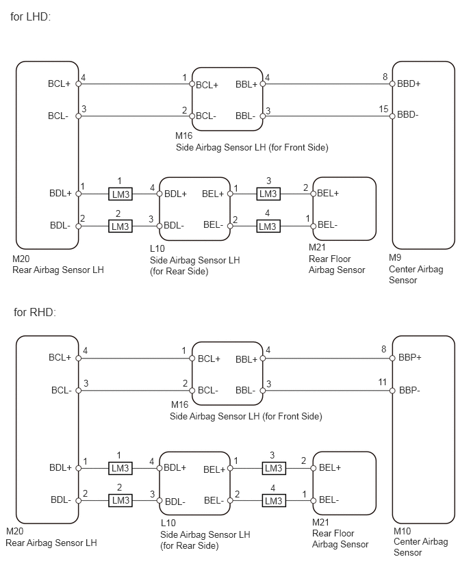
PROCEDURE
Turn the ignition switch on (IG), and wait for at least 60 seconds.
Turn the ignition switch off.
Turn the ignition switch on (IG), and wait for at least 60 seconds.
Check the DTCs (see page Vehicle Interior>SUPPLEMENTAL RESTRAINT SYSTEMS>AIRBAG SYSTEM>DTC CHECK / CLEAR).
| Result | Proceed to |
|---|---|
| DTC B1679 is output | A |
| DTC B1667 is output | B |
- HINT:
-
DTCs other than DTC B1679 and B1667 may be output at this time, but they are not related to this check.
A
B
Turn the ignition switch off.
Disconnect the cable from the negative (-) battery terminal, and wait for at least 90 seconds.
Check that the connectors are properly connected to the center airbag sensor, rear airbag sensor LH, side airbag sensor LH (for front side), side airbag sensor LH (for rear side) and the rear floor airbag sensor.
- OK:
Connectors are properly connected.
OK
NG
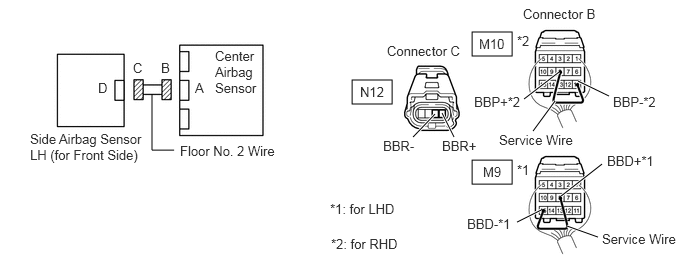
Disconnect the connectors from the center airbag sensor and the side airbag sensor (for front side).
for LHD:
Using a service wire, connect terminals M9-8 (BBD+) and M10-15 (BBD-) of connector B.
for RHD:
Using a service wire, connect terminals M10-8 (BBP+) and M10-11 (BBP-) of connector B.
- NOTICE:
-
Do not forcibly insert the service wire into the terminals of the connector when connecting them.
Measure the resistance of the wire harness side connector.
- Standard resistance:
Tester Connection Specified Condition M16-3 (BBL-) - M16-4 (BBL+) Below 1 Ω
OK
NG
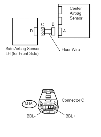
Disconnect the service wire from connector B.
Measure the resistance of the wire harness side connector.
- Standard resistance:
Tester Connection Specified Condition M16-3 (BBL-) - M16-4 (BBL+) 1 MΩ or higher
OK
NG
Connect the cable to the negative (-) battery terminal, and wait for at least 2 seconds.
Turn the ignition switch on (IG).
Measure the voltage of the wire harness side connector.
- Standard voltage:
Tester Connection Specified Condition M16-3 (BBL-) - Body ground Below 1 V M16-4 (BBL+) - Body ground
OK
NG
Turn the ignition switch off.
Disconnect the cable from the negative (-) battery terminal, and wait for at least 90 seconds.
Measure the resistance of the wire harness side connector.
- Standard resistance:
Tester Connection Specified Condition M16-3 (BBL-) - Body ground 1 MΩ or higher M16-4 (BBL+) - Body ground
OK
NG
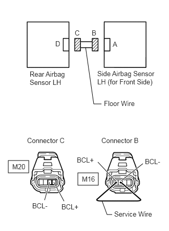
Disconnect the connectors from the side airbag sensor LH (for front side) and the rear airbag sensor LH.
Using a service wire, connect terminals M16-1 (BCL+) and M16-2 (BCL-) of connector B.
- NOTICE:
-
Do not forcibly insert the service wire into the terminals of the connector when connecting them.
Measure the resistance of the wire harness side connector.
- Standard resistance:
Tester Connection Specified Condition M20-3 (BCL-) - M20-4 (BCL+) Below 1 Ω
OK
NG
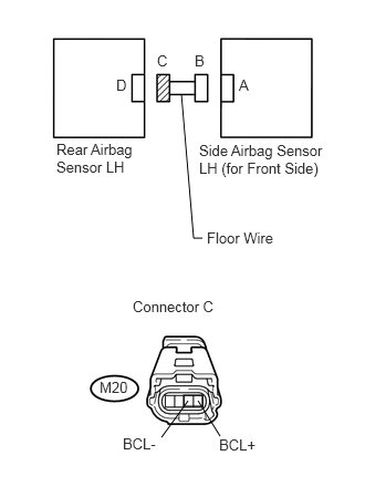
Disconnect the service wire from connector B.
Measure the resistance of the wire harness side connector.
- Standard resistance:
Tester Connection Specified Condition M20-3 (BCL-) - M20-4 (BCL+) 1 MΩ or higher
OK
NG
Connect the cable to the negative (-) battery terminal, and wait for at least 2 seconds.
Turn the ignition switch on (IG).
Measure the voltage of the wire harness side connector.
- Standard voltage:
Tester Connection Specified Condition M20-3 (BCL-) - Body ground Below 1 V M20-4 (BCL+) - Body ground
OK
NG
Turn the ignition switch off.
Disconnect the cable from the negative (-) battery terminal, and wait for at least 90 seconds.
Measure the resistance of the wire harness side connector.
- Standard resistance:
Tester Connection Specified Condition M20-3 (BCL-) - Body ground 1 MΩ or higher N20-4 (BCR+) - Body ground
OK
NG
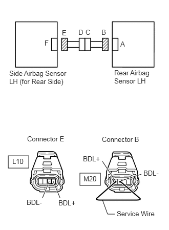
Disconnect the connectors from the rear airbag sensor LH and the side airbag sensor (for rear side).
Using a service wire, connect terminals M20-1 (BDL+) and M20-2 (BDL-) of connector B.
- NOTICE:
-
Do not forcibly insert the service wire into the terminals of the connector when connecting them.
Measure the resistance of the wire harness side connector.
- Standard resistance:
Tester Connection Specified Condition L10-3 (BDL-) - L10-4 (BDL+) Below 1 Ω
OK
NG
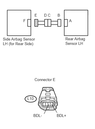
Disconnect the service wire from connector B.
Measure the resistance of the wire harness side connector.
- Standard resistance:
Tester Connection Specified Condition L10-3 (BDL-) - L10-4 (BDL+) 1 MΩ or higher
OK
NG
Connect the cable to the negative (-) battery terminal, and wait for at least 2 seconds.
Turn the ignition switch on (IG).
Measure the voltage of the wire harness side connector.
- Standard voltage:
Tester Connection Specified Condition L10-3 (BDL-) - Body ground Below 1 V L10-4 (BDL+) - Body ground
OK
NG
Turn the ignition switch off.
Disconnect the cable from the negative (-) battery terminal, and wait for at least 90 seconds.
Measure the resistance of the wire harness side connector.
- Standard resistance:
Tester Connection Specified Condition L10-3 (BDL-) - Body ground 1 MΩ or higher L10-4 (BDL+) - Body ground
OK
NG
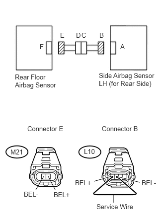
Disconnect the connectors from the side airbag sensor LH (for rear side) and the rear floor door airbag sensor.
Using a service wire, connect terminals L10-1 (BEL+) and L10-2 (BEL-) of connector B.
- NOTICE:
-
Do not forcibly insert the service wire into the terminals of the connector when connecting them.
Measure the resistance of the wire harness side connector.
- Standard resistance:
Tester Connection Specified Condition M21-1 (BEL-) - M21-2 (BEL+) Below 1 Ω
OK
NG
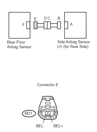
Disconnect the service wire from connector B.
Measure the resistance of the wire harness side connector.
- Standard resistance:
Tester Connection Specified Condition M21-1 (BEL-) - M21-2 (BEL+) 1 MΩ or higher
OK
NG
Connect the cable to the negative (-) battery terminal, and wait for at least 2 seconds.
Turn the ignition switch on (IG).
Measure the voltage of the wire harness side connector.
- Standard voltage:
Tester Connection Specified Condition M21-1 (BEL-) - Body ground Below 1 V M21-2 (BEL+) - Body ground
OK
NG
Turn the ignition switch off.
Disconnect the cable from the negative (-) battery terminal, and wait for at least 90 seconds.
Measure the resistance of the wire harness side connector.
- Standard resistance:
Tester Connection Specified Condition M21-1 (BEL-) - Body ground 1 MΩ or higher M21-2 (BEL+) - Body ground
OK
NG
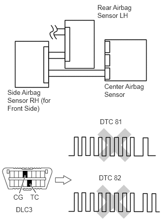
Connect the connectors to the center airbag sensor.
Interchange the side airbag sensor LH (for front side) with the side airbag sensor RH (for front side) and connect the connectors to them.
Connect the cable to the negative (-) battery terminal, and wait for at least 2 seconds.
Turn the ignition switch on (IG), and wait for at least 60 seconds.
Clear the DTCs (see page Vehicle Interior>SUPPLEMENTAL RESTRAINT SYSTEMS>AIRBAG SYSTEM>DTC CHECK / CLEAR).
Turn the ignition switch off.
Turn the ignition switch on (IG), and wait for at least 60 seconds.
Check for DTCs (see page Vehicle Interior>SUPPLEMENTAL RESTRAINT SYSTEMS>AIRBAG SYSTEM>DTC CHECK / CLEAR).
| Result | Proceed to |
|---|---|
| DTC B1676/81 and B1678/82 are not output | A |
| DTC B1678/82 is output | B |
| DTC B1676/81 is output | C |
- HINT:
-
DTCs other than DTC B1676/81 and B1678/82 may be output at this time, but they are not related to this check.
A
B
C
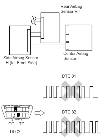
Turn the ignition switch off.
Disconnect the cable from the negative (-) battery terminal, and wait for at least 90 seconds.
Interchange the rear airbag sensor LH with the rear airbag sensor RH and connect the connectors to them.
Connect the cable to the negative (-) battery terminal, and wait for at least 2 seconds.
Turn the ignition switch on (IG), and wait for at least 60 seconds.
Clear the DTCs (see page Vehicle Interior>SUPPLEMENTAL RESTRAINT SYSTEMS>AIRBAG SYSTEM>DTC CHECK / CLEAR).
Turn the ignition switch off.
Turn the ignition switch on (IG), and wait for at least 60 seconds.
Check the DTCs (see page Vehicle Interior>SUPPLEMENTAL RESTRAINT SYSTEMS>AIRBAG SYSTEM>DTC CHECK / CLEAR).
| Result | Proceed to |
|---|---|
| DTC B1676/81 and B1678/82 are not output | A |
| DTC B1678/82 is output | B |
| DTC B1676/81 is output | C |
- HINT:
-
DTCs other than DTC B1676/81 and B1678/82 may be output at this time, but they are not related to this check.
A
B
C
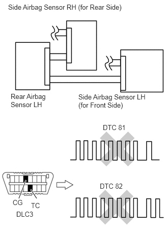
Turn the ignition switch off.
Disconnect the cable from the negative (-) battery terminal, and wait for at least 90 seconds.
Interchange the side airbag sensor LH (for rear side) with the side airbag sensor RH (for rear side) and connect the connectors to them.
Connect the cable to the negative (-) battery terminal, and wait for at least 2 seconds.
Turn the ignition switch on (IG), and wait for at least 60 seconds.
Clear the DTCs (see page Vehicle Interior>SUPPLEMENTAL RESTRAINT SYSTEMS>AIRBAG SYSTEM>DTC CHECK / CLEAR).
Turn the ignition switch off.
Turn the ignition switch on (IG), and wait for at least 60 seconds.
Check the DTCs (see page Vehicle Interior>SUPPLEMENTAL RESTRAINT SYSTEMS>AIRBAG SYSTEM>DTC CHECK / CLEAR).
| Result | Proceed to |
|---|---|
| DTC B1676/81 and B1678/82 are not output | A |
| DTC B1678/82 is output | B |
| DTC B1676/81 is output | C |
- HINT:
-
DTCs other than DTC B1676/81 and B1678/82 may be output at this time, but they are not related to this check.
A
B
C
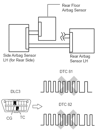
Turn the ignition switch off.
Disconnect the cable from the negative (-) battery terminal, and wait for at least 90 seconds.
Interchange the rear floor airbag sensor with the center floor airbag sensor and connect the connectors to them.
Connect the cable to the negative (-) battery terminal, and wait for at least 2 seconds.
Turn the ignition switch on (IG), and wait for at least 60 seconds.
Clear the DTCs (see page Vehicle Interior>SUPPLEMENTAL RESTRAINT SYSTEMS>AIRBAG SYSTEM>DTC CHECK / CLEAR).
Turn the ignition switch off.
Turn the ignition switch on (IG), and wait for at least 60 seconds.
Check the DTCs (see page Vehicle Interior>SUPPLEMENTAL RESTRAINT SYSTEMS>AIRBAG SYSTEM>DTC CHECK / CLEAR).
| Result | Proceed to |
|---|---|
| DTC B1676/81 and B1678/82 are not output | A |
| DTC B1678/82 is output | B |
| DTC B1676/81 is output | C |
- HINT:
-
DTCs other than DTC B1676/81 and B1678/82 may be output at this time, but they are not related to this check.
A
B
C
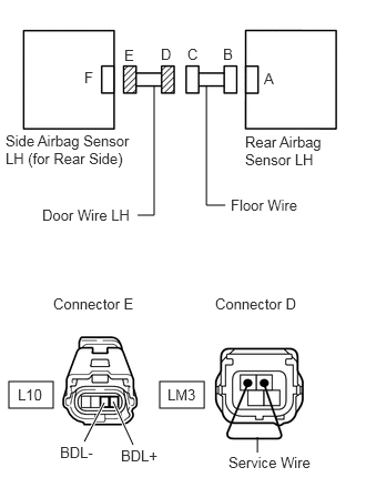
Disconnect the door wire connector from the floor wire.
Using a service wire, connect terminals LM3-1 and LM3-2 of connector D.
- NOTICE:
-
Do not forcibly insert the service wire into the terminals of the connector when connecting them.
Measure the resistance of the wire harness side connector.
- Standard resistance:
Tester Connection Specified Condition L10-3 (BDL-) - L10-4 (BDL+) Below 1 Ω
NG
OK
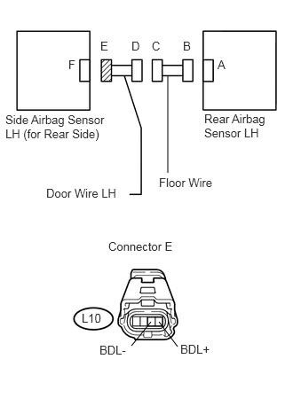
Disconnect the door wire connector from the floor wire.
Measure the resistance of the wire harness side connector.
- Standard resistance:
Tester Connection Specified Condition L10-3 (BDL-) - L10-4 (BDL+) 1 MΩ or higher
NG
OK
Turn the ignition switch off.
Disconnect the cable from the negative (-) battery terminal, and wait for at least 90 seconds.
Disconnect the door wire connector from the floor wire.
Connect the cable to the negative (-) battery terminal, and wait for at least 2 seconds.
Turn the ignition switch on (IG).
Measure the voltage of the wire harness side connector.
- Standard voltage:
Tester Connection Specified Condition L10-3 (BDL-) - Body ground Below 1 V L10-4 (BDL+) - Body ground
NG
OK
Disconnect the door wire connector from the floor wire.
Measure the resistance of the wire harness side connector.
- Standard resistance:
Tester Connection Specified Condition L10-3 (BDL-) - Body ground 1 MΩ or higher L10-4 (BDL+) - Body ground
NG
OK
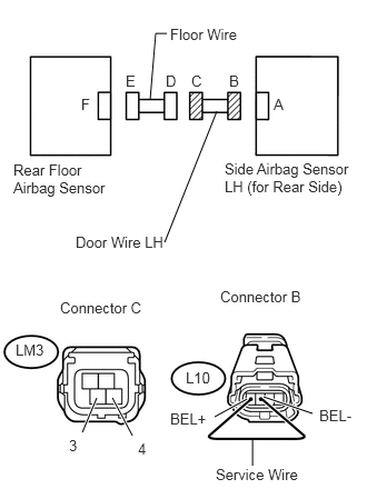
Disconnect the door wire connector from the floor wire.
Using a service wire, connect terminals L10-1 (BEL+) and L10-2 (BEL-) of connector B.
- NOTICE:
-
Do not forcibly insert the service wire into the terminals of the connector when connecting them.
Measure the resistance of the wire harness side connector.
- Standard resistance:
Tester Connection Specified Condition LM3-3 - LM3-4 Below 1 Ω
NG
OK
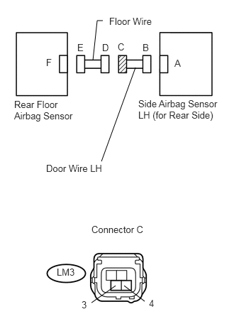
Disconnect the door wire connector from the floor wire.
Measure the resistance of the wire harness side connector.
- Standard resistance:
Tester Connection Specified Condition LM3-3 - LM3-4 1 MΩ or higher
NG
OK
Turn the ignition switch off.
Disconnect the cable from the negative (-) battery terminal, and wait for at least 90 seconds.
Disconnect the door wire connector from the floor wire.
Connect the cable to the negative (-) battery terminal, and wait for at least 2 seconds.
Turn the ignition switch on (IG).
Measure the voltage of the wire harness side connector.
- Standard voltage:
Tester Connection Specified Condition LM3-3 - Body ground Below 1 V LM3-4 - Body ground
NG
OK
Disconnect the door wire connector from the floor wire.
Measure the resistance of the wire harness side connector.
- Standard resistance:
Tester Connection Specified Condition LM3-3 - Body ground 1 MΩ or higher LM3-4 - Body ground
NG
OK