Home › Vehicle Interior › LIGHTING › LIGHTING SYSTEM(except LED Headlight) › 2013.04–2016.05
RM24M0E _58 Vehicle Interior _059564 LIGHTING _0291933 LIGHTING SYSTEM(except LED Headlight) C

LIGHTING  LIGHTING SYSTEM(except LED Headlight)  B2416  Height Control Sensor Malfunction  


DESCRIPTION

The AFS ECU receives a vehicle height signal from the height control sensor.

DTC No. DTC Detection Condition Trouble Area
B2416 When one of conditions is met:
·

Height control sensor malfunction

·

Abnormal height control sensor power supply voltage

·

Malfunction in communication line between height control sensor and AFS ECU


·

AFS ECU

·

Height control sensor

·

Wire harness


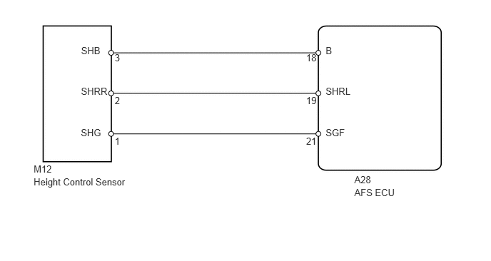
WIRING DIAGRAM

E132264E02
0.491,2.384 1.924,2.554 1.433,0.171 10 M12 0.491,2.571 1.924,2.741 1.433,0.171 10 Height Control Sensor 1.184,0.653 1.578,0.829 0.394,0.176 10 SHB 1.674,0.765 2.068,0.941 0.394,0.176 10 3 1.674,1.387 2.068,1.564 0.394,0.176 10 2 1.674,1.984 2.068,2.160 0.394,0.176 10 1 4.468,0.765 4.645,0.941 0.177,0.176 10 18 4.468,1.387 4.645,1.564 0.177,0.176 10 19 4.468,1.984 4.645,2.160 0.177,0.176 10 21 1.182,1.248 1.601,1.409 0.420,0.161 10 SHRR 1.18,1.85 1.573,2.017 0.392,0.167 10 SHG 4.753,0.653 5.187,0.805 0.434,0.153 10 B 4.753,1.248 5.173,1.413 0.420,0.165 10 SHRL 4.753,1.85 5.145,2.009 0.392,0.159 10 SGF 5.172,2.538 6.265,2.712 1.093,0.174 10 A28 5.172,2.725 6.265,2.898 1.093,0.174 10 AFS ECU

PROCEDURE

1.READ VALUE USING INTELLIGENT TESTER (HEIGHT CONTROL SENSOR)
a.

Connect the intelligent tester to the DLC3.


b.

Turn the ignition switch on (IG) and the tester ON.


c.

Read the Data List according to the prompts displayed on the tester.

AFS ECU
Item Tester Details Normal Condition Diagnostic Note
Height Sens Pw Supply Val Height control sensor power supply value / Min.: 0 V, Max.: 5 V Power supply voltage to height control sensor -
Rr Height Sens Signal Val Rear height control sensor signal / Min.: 0 V, Max.: 5 V Height control sensor vehicle height value -

OK:

Tester indicates normal value.


A

2.INSPECT HEIGHT CONTROL SENSOR

B

4.REPLACE AFS ECU
2.INSPECT HEIGHT CONTROL SENSOR
a.
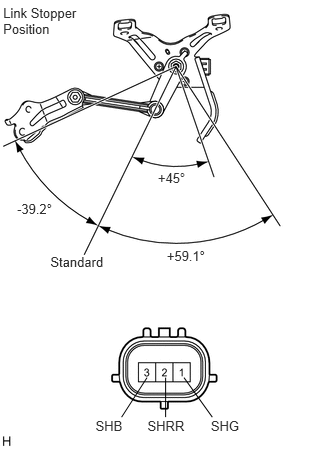
E127511E04
0.177,2.093 0.731,2.262 0.554,0.169 10 -39.2° 1.737,2.585 2.291,2.754 0.554,0.169 10 +59.1° 1.644,1.766 2.093,1.935 0.449,0.169 10 +45° 0.524,2.641 1.130,2.786 0.606,0.145 10 Standard 0.995,4.355 1.326,4.500 0.331,0.145 10 SHB 1.536,4.355 2.027,4.500 0.490,0.145 10 SHRR 2.196,4.355 2.528,4.500 0.331,0.145 10 SHG 0.033,0.054 0.844,0.374 0.811,0.320 10 Link Stopper Position 1.725,3.933 1.725,4.345 false 1.916,3.933 2.211,4.345 false 1.531,3.933 1.266,4.345 false

Disconnect the M12 sensor connector.


b.

Connect the 3 dry cell batteries (1.5 V) in series.


c.

Connect the battery positive (+) lead to terminal 3 of the sensor and the battery negative (-) lead to terminal 1 of the sensor.


d.

Measure the voltage between 3 and 1 while slowly moving the link up and down.

Standard voltage:
Tester Connection Condition Specified Condition
3 (SHB) - 1 (SHG) +45° (High) 4.05 V
3 (SHB) - 1 (SHG) 0° (Normal) 2.25 V
3 (SHB) - 1 (SHG) -39.2° (Low) 0.68 V


OK

3.CHECK WIRE HARNESS (AFS ECU - HEIGHT CONTROL SENSOR)

NG

5.REPLACE HEIGHT CONTROL SENSOR
3.CHECK WIRE HARNESS (AFS ECU - HEIGHT CONTROL SENSOR)
a.
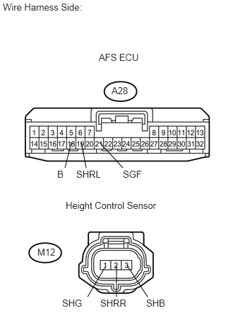
U189884E02
1.052,2.094 0.958,2.469 false 1.198,2.094 1.271,2.469 false 1.469,2.094 1.813,2.469 false 1.563,3.906 1.292,4.365 false 1.719,3.906 1.719,4.365 false 1.875,3.906 2.177,4.365 false 0.042,0.021 1.406,0.188 1.365,0.167 10 false Wire Harness Side: 1.458,0.76 2.125,0.927 0.667,0.167 10 false AFS ECU 0.917,4.375 1.26,4.542 0.344,0.167 10 false SHG 1.479,4.375 1.948,4.542 0.469,0.167 10 false SHRR 2.156,4.375 2.5,4.542 0.344,0.167 10 false SHB 1.813,2.479 2.156,2.646 0.344,0.167 10 false SGF 1.125,2.479 1.594,2.646 0.469,0.167 10 false SHRL 0.844,2.479 1.021,2.646 0.177,0.167 10 false B 0.969,2.938 2.49,3.167 1.521,0.229 10 false Height Control Sensor 1.646,1.25 1.938,1.417 0.292,0.167 10 false A28 0.552,3.625 0.844,3.792 0.292,0.167 10 false M12

Disconnect the A28 ECU connector.


b.

Disconnect the M12 sensor connector.


c.

Measure the resistance of the wire harness side connectors.

Standard resistance:
Tester Connection Specified Condition
A28-18 (B) - M12-3 (SHB) Below 1 Ω
A28-19 (SHRL) - M12-2 (SHRR) Below 1 Ω
A28-21 (SGF) - M12-1 (SHG) Below 1 Ω
A28-18 (B) or M12-3 (SHB) - Body ground 10 kΩ or higher
A28-19 (SHRL) or M12-2 (SHRR) - Body ground 10 kΩ or higher
A28-21 (SGF) or M12-1 (SHG) - Body ground 10 kΩ or higher


OK

4.REPLACE AFS ECU

NG

REPAIR OR REPLACE HARNESS OR CONNECTOR

4.REPLACE AFS ECU

NEXT

6.PERFORM INITIALIZATION
5.REPLACE HEIGHT CONTROL SENSOR

NEXT

6.PERFORM INITIALIZATION

NEXT

END