Home › Vehicle Interior › LIGHTING › LIGHTING SYSTEM(except LED Headlight) › from 2016.05
RM24M0E _58 Vehicle Interior _059564 LIGHTING _0291933 LIGHTING SYSTEM(except LED Headlight) J

LIGHTING  LIGHTING SYSTEM(except LED Headlight)  Headlight (HI-BEAM) Circuit  


DESCRIPTION

The main body ECU receives headlight (HIGH) switch information from the headlight dimmer switch, and controls the headlight dimmer relay (marking: DIM).

WIRING DIAGRAM
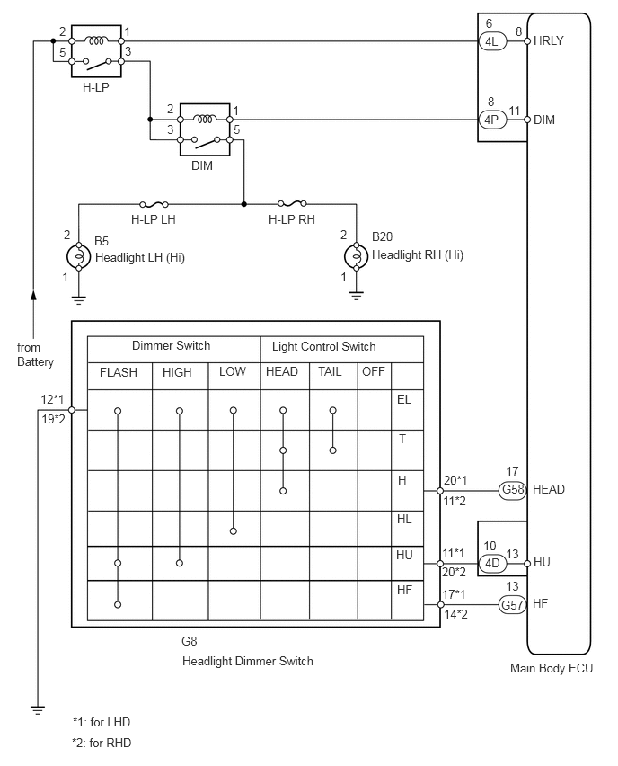
E132455E09
5.917,7.656 6.938,7.823 1.021,0.167 10 false Main Body ECU 0.958,0.927 1.313,1.094 0.354,0.167 10 false H-LP 6.188,1.302 6.542,1.469 0.354,0.167 10 false DIM 1.521,2.458 2.208,2.625 0.688,0.167 10 false H-LP LH 1.094,2.708 1.781,2.875 0.688,0.167 10 false B5 1.104,2.896 2.281,3.063 1.177,0.167 10 false Headlight LH (Hi) 1.531,3.917 2.708,4.083 1.177,0.167 10 false Dimmer Switch 2.104,7.344 3.281,7.51 1.177,0.167 10 false G8 2.115,7.573 3.99,7.74 1.875,0.167 10 false Headlight Dimmer Switch 0.844,8.281 1.563,8.448 0.719,0.167 10 false *1: for LHD 1.156,4.229 1.635,4.396 0.479,0.167 10 false FLASH 1.885,4.229 2.365,4.396 0.479,0.167 10 false HIGH 2.542,4.219 2.885,4.385 0.344,0.167 10 false LOW 6.177,5.583 6.615,5.75 0.438,0.167 10 false HEAD 3.688,4.219 4.031,4.385 0.344,0.167 10 false TAIL 4.198,4.219 4.542,4.385 0.344,0.167 10 false OFF 4.604,4.542 4.948,4.708 0.344,0.167 10 false EL 4.625,5 4.969,5.167 0.344,0.167 10 false T 4.615,5.479 4.958,5.646 0.344,0.167 10 false H 4.604,5.927 4.948,6.094 0.344,0.167 10 false HL 4.594,6.344 4.938,6.51 0.344,0.167 10 false HU 4.604,6.75 4.948,6.917 0.344,0.167 10 false HF 3.156,3.927 4.552,4.094 1.396,0.167 10 false Light Control Switch 0.469,4.542 0.844,4.708 0.375,0.167 10 false 12*1 3.948,3.125 4.094,3.292 0.146,0.167 10 false 1 3.948,2.635 4.094,2.802 0.146,0.167 10 false 2 4.313,2.656 5,2.823 0.688,0.167 10 false B20 4.313,2.865 5.49,3.031 1.177,0.167 10 false Headlight RH (Hi) 0.719,3.125 0.865,3.292 0.146,0.167 10 false 1 0.74,2.635 0.885,2.802 0.146,0.167 10 false 2 0.479,4.771 0.854,4.938 0.375,0.167 10 false 19*2 5.146,5.479 5.521,5.646 0.375,0.167 10 false 20*1 5.625,0.396 5.802,0.563 0.177,0.167 10 false 4L 6.188,0.385 6.75,0.552 0.563,0.167 10 false HRLY 5.635,0.188 5.76,0.354 0.125,0.167 10 false 6 5.615,1.302 5.813,1.469 0.198,0.167 10 false 4P 2.219,1.833 2.708,2 0.49,0.167 10 false DIM 5.979,0.281 6.104,0.448 0.125,0.167 10 false 8 5.656,1.094 5.781,1.26 0.125,0.167 10 false 8 2.698,1.198 2.823,1.365 0.125,0.167 10 false 1 2.708,1.417 2.833,1.583 0.125,0.167 10 false 5 1.938,1.177 2.063,1.344 0.125,0.167 10 false 2 1.938,1.417 2.063,1.583 0.125,0.167 10 false 3 1.438,0.281 1.563,0.448 0.125,0.167 10 false 1 1.448,0.51 1.573,0.677 0.125,0.167 10 false 3 0.688,0.281 0.813,0.448 0.125,0.167 10 false 2 0.688,0.521 0.813,0.688 0.125,0.167 10 false 5 5.823,5.583 6.104,5.75 0.281,0.167 10 false G58 3.083,4.219 3.573,4.385 0.49,0.167 10 false HEAD 5.865,5.375 6.083,5.542 0.219,0.167 10 false 17 5.625,6.438 5.906,6.604 0.281,0.167 10 false 4D 6.188,6.427 6.677,6.594 0.49,0.167 10 false HU 5.604,6.24 5.823,6.406 0.219,0.167 10 false 10 5.813,6.927 6.094,7.094 0.281,0.167 10 false G57 6.177,6.906 6.667,7.073 0.49,0.167 10 false HF 5.865,6.708 6.083,6.875 0.219,0.167 10 false 13 5.865,6.333 6.083,6.5 0.219,0.167 10 false 13 5.896,1.198 6.115,1.365 0.219,0.167 10 false 11 5.135,5.719 5.51,5.885 0.375,0.167 10 false 11*2 5.125,6.323 5.5,6.49 0.375,0.167 10 false 11*1 5.125,6.542 5.5,6.708 0.375,0.167 10 false 20*2 5.125,6.802 5.5,6.969 0.375,0.167 10 false 17*1 5.146,7.031 5.521,7.198 0.375,0.167 10 false 14*2 0.198,3.938 0.708,4.302 0.51,0.365 10 false from Battery 3.115,2.458 3.802,2.625 0.688,0.167 10 false H-LP RH 0.833,8.521 1.615,8.698 0.781,0.177 10 false *2: for RHD

PROCEDURE

1.CHECK HEADLIGHT
a.

Check that the headlights (Low) come on when the light control switch is in the HEAD position.

OK:

Headlights (Low) come on.


OK

2.PERFORM ACTIVE TEST USING GTS (HEADLIGHT HI)

NG

2.PERFORM ACTIVE TEST USING GTS (HEADLIGHT HI)
a.

Connect the GTS to the DLC3.


b.

Turn the engine switch on (IG).


c.

Turn the GTS on.


d.

Enter the following menus: Body Electrical / Main Body / Active Test.


e.

Perform the Active Test according to the display on the GTS.

Main Body
Item Test Details Diagnostic Note
Headlight Hi Turn headlight dimmer switch to HI position:
ON / OFF
-

OK:

Headlights (Hi) come on.


NG

3.INSPECT FUSE (H-LP LH, H-LP RH)

OK

9.INSPECT HEADLIGHT DIMMER SWITCH
3.INSPECT FUSE (H-LP LH, H-LP RH)
a.

Remove the H-LP LH and H-LP RH fuses from the engine room No. 2 relay block.


b.

Measure the resistance of the fuses.

Standard Resistance:

Below 1 Ω


OK

4.INSPECT HEADLIGHT DIMMER RELAY (Marking: DIM)

NG

REPLACE FUSE

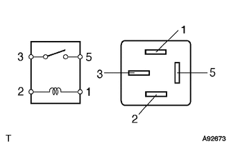
4.INSPECT HEADLIGHT DIMMER RELAY (Marking: DIM)
B112776

a.

Remove the headlight dimmer relay from the engine room No. 2 relay block.


b.

Measure the resistance of the relay.

Standard Resistance:
Tester Connection Specified Condition
3 - 5 10 kΩ or higher
3 - 5 Below 1 Ω
(Battery voltage applied to terminals 1 and 2)


OK

5.INSPECT HEADLIGHT BULB (HI-BEAM)

NG

REPLACE HEADLIGHT DIMMER RELAY

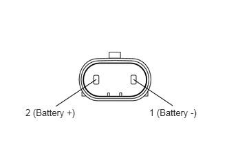
5.INSPECT HEADLIGHT BULB (HI-BEAM)
C128857E02
1.458,1.198 0.844,1.604 false 2.021,1.198 2.615,1.594 false 0.385,1.615 1.354,1.792 0.969,0.177 10 false 2 (Battery +) 2.26,1.615 3.177,1.76 0.917,0.146 10 false 1 (Battery -)

a.

Remove the headlight bulbs (Hi-beam).


b.

Connect the positive (+) lead from the battery to terminal 2 and the negative (-) lead to terminal 1. Then check that the bulb illuminates.

OK:

Bulb illuminates.


OK

6.CHECK WIRE HARNESS (MAIN BODY ECU - BATTERY)

NG

REPLACE HEADLIGHT BULB (HI-BEAM)

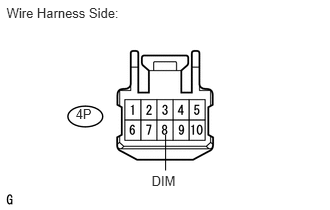
6.CHECK WIRE HARNESS (MAIN BODY ECU - BATTERY)
U190042E01
0.068,0.052 1.412,0.208 1.343,0.156 10 Wire Harness Side: 1.579,1.802 1.879,1.958 0.299,0.156 10 DIM 0.788,1.108 0.975,1.289 0.187,0.181 10 4P 1.725,1.406 1.725,1.776 false

a.

Disconnect the 4P ECU connector.


b.

Measure the voltage of the wire harness side connector.

Standard Voltage:
Tester Connection Condition Specified Condition
4P-8 (DIM) - Body ground Light control switch HEAD 11 to 14 V


OK

7.CHECK WIRE HARNESS (HEADLIGHT DIMMER RELAY - BATTERY)

NG

REPAIR OR REPLACE HARNESS OR CONNECTOR

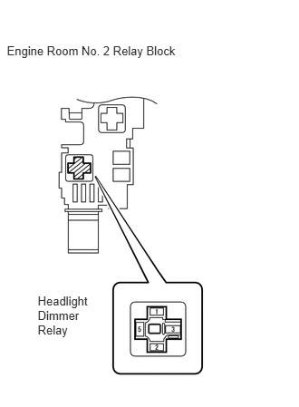
7.CHECK WIRE HARNESS (HEADLIGHT DIMMER RELAY - BATTERY)
B141821E01
0.079,0.504 2.127,0.660 2.048,0.156 10 Engine Room No. 2 Relay Block 0.433,3.378 1.096,3.919 0.663,0.542 10 Headlight Dimmer Relay

a.

Remove the headlight dimmer relay from the engine room No. 2 relay block.


b.

Measure the voltage of the relay block.

Standard Voltage:
Tester Connection Condition Specified Condition
Relay block No. 2 headlight dimmer relay terminal 3 - Body ground Light control switch HEAD 11 to 14 V


OK

8.CHECK WIRE HARNESS (BULB - HEADLIGHT DIMMER RELAY AND BODY GROUND)

NG

REPAIR OR REPLACE HARNESS OR CONNECTOR

8.CHECK WIRE HARNESS (BULB - HEADLIGHT DIMMER RELAY AND BODY GROUND)
a.

Disconnect the B5 and B20 headlight (Hi-beam) bulb connectors.


b.

Remove the headlight dimmer relay from the engine room No. 2 relay block.


c.

Measure the resistance of the wire harness side connectors.

Standard Resistance:
Tester Connection Specified Condition
B5-2 - Relay block No. 2 headlight dimmer relay terminal 5 Below 1 Ω
B5-2 or relay block No. 2 headlight dimmer relay terminal 5 - Body ground 10 kΩ or higher
B20-2 - Relay block No. 2 headlight dimmer relay terminal 5 Below 1 Ω
B20-2 or relay block No. 2 headlight dimmer relay terminal 5 - Body ground 10 kΩ or higher
B5-1 - Body ground Below 1 Ω
B20-1 - Body ground Below 1 Ω


OK

REPLACE MAIN BODY ECU

NG

REPAIR OR REPLACE HARNESS OR CONNECTOR

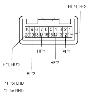
9.INSPECT HEADLIGHT DIMMER SWITCH
B128006E54
0.927,1.229 0.427,1.698 0.427,1.698 0.417,2.115 false 2.469,1.219 2.802,1.146 2.802,1.146 2.813,0.396 false 1.458,1.24 1.448,1.656 false 1.958,1.26 1.948,2.083 false 1.125,1.24 1.115,2.438 false 2.292,1.229 2.302,1.677 false 0.094,2.177 0.781,2.396 0.688,0.219 10 false H*1, HU*2 2.385,0.156 3.125,0.344 0.74,0.188 10 false HU*1, H*2 1.302,1.708 1.75,1.865 0.448,0.156 10 false HF*1 2.188,1.729 2.542,1.906 0.354,0.177 10 false EL*1 1.771,2.115 2.25,2.313 0.479,0.198 10 false HF*2 0.938,2.5 1.344,2.646 0.406,0.146 10 false EL*2 0.167,2.833 0.896,3 0.729,0.167 10 false *1: for LHD 0.135,3.094 0.896,3.25 0.76,0.156 10 false *2: for RHD

a.

Remove the headlight dimmer switch.


b.

Measure the resistance of the switch.

Standard Resistance:
for LHD
Tester Connection Condition Specified Condition
20 (H) - 12 (EL) Light control switch HEAD Below 1 Ω
11 (HU) - 12 (EL) Headlight dimmer switch HIGH Below 1 Ω
11 (HU) - 12 (EL) Headlight dimmer switch LOW 10 kΩ or higher
17 (HF) - 12 (EL) Headlight dimmer switch FLASH Below 1 Ω
17 (HF) - 12 (EL) Headlight dimmer switch except FLASH 10 kΩ or higher

for RHD
Tester Connection Condition Specified Condition
11 (H) - 19 (EL) Light control switch HEAD Below 1 Ω
20 (HU) - 19 (EL) Headlight dimmer switch HIGH Below 1 Ω
20 (HU) - 19 (EL) Headlight dimmer switch LOW 10 kΩ or higher
14 (HF) - 19 (EL) Headlight dimmer switch FLASH Below 1 Ω
14 (HF) - 19 (EL) Headlight dimmer switch except FLASH 10 kΩ or higher


OK

10.CHECK WIRE HARNESS (HEADLIGHT DIMMER SWITCH - MAIN BODY ECU AND BODY GROUND)

NG

REPLACE HEADLIGHT DIMMER SWITCH ASSEMBLY

10.CHECK WIRE HARNESS (HEADLIGHT DIMMER SWITCH - MAIN BODY ECU AND BODY GROUND)
a.

Disconnect the G8 headlight dimmer switch connector.


b.

Disconnect the 4D, G57 and G58 main body ECU connectors.


c.

Measure the resistance of the wire harness side connectors.

Standard Resistance:
for LHD
Tester Connection Specified Condition
G8-20 (H) - G58-17 (HEAD) Below 1 Ω
G8-20 (H) or G58-17 (HEAD) - Body ground 10 kΩ or higher
G8-17 (HF) - G57-13 (HF) Below 1 Ω
G8-17 (HF) or G57-13 (HF) - Body ground 10 kΩ or higher
G8-11 (HU) - 4D-10 (HU) Below 1 Ω
G8-11 (HU) or 4D-10 (HU) - Body ground 10 kΩ or higher
G8-12 (EL) - Body ground Below 1 Ω

for RHD
Tester Connection Specified Condition
G8-11 (H) - G57-17 (HEAD) Below 1 Ω
G8-11 (H) or G57-17 (HEAD) - Body ground 10 kΩ or higher
G8-14 (HF) - G57-13 (HF) Below 1 Ω
G8-14 (HF) or G57-13 (HF) - Body ground 10 kΩ or higher
G8-20 (HU) - 4D-10 (HU) Below 1 Ω
G8-20 (HU) or 4D-10 (HU) - Body ground 10 kΩ or higher
G8-19 (EL) - Body ground Below 1 Ω


OK

PROCEED TO NEXT CIRCUIT INSPECTION SHOWN IN PROBLEM SYMPTOMS TABLE

NG

REPAIR OR REPLACE HARNESS OR CONNECTOR