SEAT REAR NO. 2 SEAT ASSEMBLY(for Power Stowing Seat Type LH Side) INSTALLATION
PROCEDURE

 79040
1.INSTALL NO. 3 SEAT LEG ASSEMBLY LH
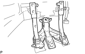
Engage the seat leg to the floor front side stud bolt hole.
2.INSTALL REAR NO. 2 SEAT ASSEMBLY LH
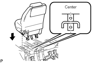
Place the seat onto the lock striker.
Fully lock the seat to the lock striker.
Connect the connector.
- HINT:
- ·
Confirm that the seat is firmly locked to the lock striker.
·The rear leg should be set to the center of the lock striker.
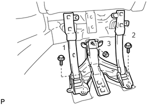
Temporarily install bolt 2.
Install bolt 1.
- Torque:
- 29 N*m (296 kgf*cm, 21 ft.*lbf)
Tighten bolt 2.
- Torque:
- 29 N*m (296 kgf*cm, 21 ft.*lbf)
Install nut 3.
- Torque:
- 29 N*m (296 kgf*cm, 21 ft.*lbf)
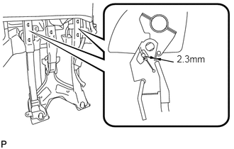
Adjust the seat leg and stopper clearance as shown in the illustration.
- Standard clearance:
2.3 mm (0.091 in.)
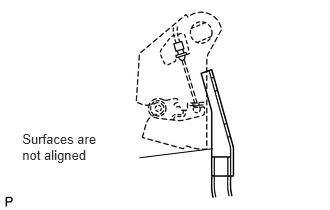
If the lower surface of the stopper is not aligned with the seat leg:
Connect cable to negative battery terminal.
Lift the lever (A) shown in the illustration and press the button on the fold seat switch, indicated by the arrow in the illustration, to adjust the alignment.
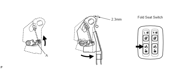
- Standard clearance:
2.3 mm (0.091 in.)
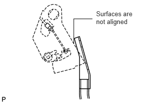
If the upper surface of the stopper is not aligned with the seat leg:
Connect cable to negative battery terminal.
Press the button on the fold seat switch, indicated by the arrow in the illustration, to adjust the alignment.
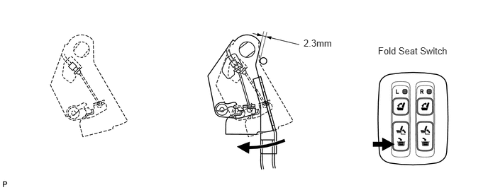
- Standard clearance:
2.3 mm (0.091 in.)
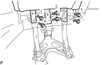
While pressing against the arms of the seat legs, tighten the bolts in the order shown in the illustration.
- Torque:
- 29 N*m (296 kgf*cm, 21 ft.*lbf)
- NOTICE:
-
If the seat leg and stopper surfaces are not aligned properly, the lock will malfunction when the seat is operated.
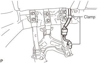
Attach the 2 clamps to install the seat leg.
79273
3.INSTALL NO. 2 SEAT HINGE COVER
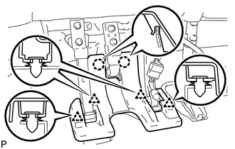
Attach the 2 claws.
Attach the 2 clips to install the hinge cover.
79384
4.INSTALL NO. 3 SEAT LEG COVER REAR LH
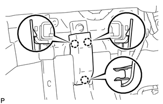
Attach the 3 claws to install the leg cover.
79236B
5.INSTALL NO. 2 SEAT LEG COVER LH
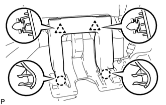
Attach the 2 claws.
Attach the 2 clips to install the leg cover.
6.CONNECT CABLE TO NEGATIVE BATTERY TERMINAL
7.CHECK REAR NO. 2 SEAT STOWING FUNCTION (for Power Seat Type LH Side)
8.PERFORM INITIALIZATION
Perform initialization (see page General>INTRODUCTION>REPAIR INSTRUCTION>INITIALIZATION ).
- NOTICE:
-
Certain systems need to be initialized after disconnecting and reconnecting the cable from the negative (-) battery terminal.