Home › Vehicle Interior › DOOR LOCK › SMART ENTRY AND START SYSTEM › from 2016.05
RM24M0E _58 Vehicle Interior _059568 DOOR LOCK _0292017 SMART ENTRY AND START SYSTEM J

DOOR LOCK  SMART ENTRY AND START SYSTEM  Driver Side Door Entry Unlock Function does not Operate  


DESCRIPTION

When an ID code from the door electrical key oscillator LH matches the ID code from the key, the certification ECU outputs an SEL signal (Lo when output) to the door electrical key oscillator LH, activates the touch sensor located on the backside of the outside door handle, and enters unlock standby mode. When the touch sensor is touched, the door electrical key oscillator LH sends a SENS signal (Lo when output) to the certification ECU and the certification ECU sends an unlock signal to the driver side door lock.

WIRING DIAGRAM
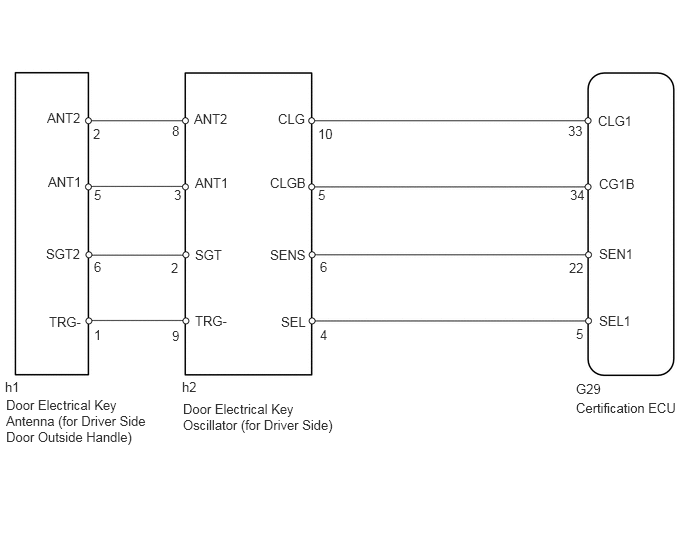
B144907E13
6.229,1.177 6.604,1.354 0.375,0.177 10 false CLG1 6.24,1.833 6.635,2.01 0.396,0.177 10 false CG1B 6.24,2.563 6.615,2.74 0.375,0.177 10 false SEN1 6.24,3.26 6.594,3.438 0.354,0.177 10 false SEL1 2.896,1.156 3.198,1.333 0.302,0.177 10 false CLG 2.813,1.823 3.208,2 0.396,0.177 10 false CLGB 2.813,2.573 3.208,2.75 0.396,0.177 10 false SENS 2.927,3.271 3.208,3.448 0.281,0.177 10 false SEL 2.021,1.156 2.396,1.333 0.375,0.177 10 false ANT2 2.031,1.823 2.406,2 0.375,0.177 10 false ANT1 2.031,2.573 2.333,2.75 0.302,0.177 10 false SGT 2.031,3.26 2.385,3.438 0.354,0.177 10 false TRG- 0.49,1.146 0.865,1.323 0.375,0.177 10 false ANT2 0.969,1.313 1.188,1.49 0.219,0.177 10 false 2 3.313,1.313 3.542,1.49 0.229,0.177 10 false 10 5.917,1.281 6.146,1.458 0.229,0.177 10 false 33 5.938,1.948 6.167,2.125 0.229,0.177 10 false 34 5.927,2.708 6.156,2.885 0.229,0.177 10 false 22 1.792,1.281 2.01,1.458 0.219,0.177 10 false 8 1.813,1.948 2.031,2.125 0.219,0.177 10 false 3 1.781,2.708 2,2.885 0.219,0.177 10 false 2 1.792,3.417 2.01,3.594 0.219,0.177 10 false 9 0.979,1.948 1.198,2.125 0.219,0.177 10 false 5 3.313,1.948 3.531,2.125 0.219,0.177 10 false 5 6,3.396 6.219,3.573 0.219,0.177 10 false 5 0.979,2.698 1.198,2.875 0.219,0.177 10 false 6 3.333,2.698 3.552,2.875 0.219,0.177 10 false 6 3.333,3.406 3.552,3.583 0.219,0.177 10 false 4 0.979,3.406 1.198,3.583 0.219,0.177 10 false 1 0.5,1.813 0.875,1.99 0.375,0.177 10 false ANT1 0.479,2.563 0.896,2.74 0.417,0.177 10 false SGT2 0.51,3.271 0.865,3.448 0.354,0.177 10 false TRG- 1.896,3.948 2.49,4.135 0.594,0.188 10 false h2 0.052,3.948 0.625,4.167 0.573,0.219 10 false h1 6,3.969 6.729,4.115 0.729,0.146 10 false G29 0.063,4.135 1.625,4.729 1.563,0.594 10 false Door Electrical Key Antenna (for Driver Side Door Outside Handle) 1.906,4.177 3.646,4.667 1.74,0.49 10 false Door Electrical Key Oscillator (for Driver Side) 6,4.167 7.125,4.542 1.125,0.375 10 false Certification ECU

PROCEDURE

1.TROUBLE AREA CONFIRMATION
a.

Check the driver door entry lock and unlock function operation.

Condition Proceed to
Driver door entry lock function operates normally A
Driver door entry lock and unlock functions do not operate B


A

2.CHECK FOR DTC

B

REFER TO " Driver door entry lock and unlock functions do not operate " FLOWCHART

2.CHECK FOR DTC
a.

Connect the intelligent tester to the DLC3.


b.

Turn the ignition switch on (IG) and turn the tester ON.


c.

By following the tester screen display, check whether any DTCs are output.

Result:
Result Proceed to
DTC output (for 2AZ-FE) A
DTC output (for 2GR-FE) B
No DTC output C


C

3.CHECK MANUAL DOOR UNLOCK OPERATION

A

B

3.CHECK MANUAL DOOR UNLOCK OPERATION
a.

Check that all the doors unlock when the door control switch (for manual operation) is turned to UNLOCK.

OK:

All doors can be unlocked with door control switch.


OK

4.CHECK WIRELESS DOOR LOCK CONTROL OPERATION

NG

4.CHECK WIRELESS DOOR LOCK CONTROL OPERATION
a.

Check that the wireless door lock and unlock functions operate normally.

OK:

Wireless door lock and unlock functions operate normally.


OK

5.READ VALUE USING INTELLIGENT TESTER (DOOR COURTESY LIGHT SWITCH)

NG

GO TO WIRELESS DOOR LOCK CONTROL SYSTEM (w/ SMART ENTRY AND START SYSTEM)

5.READ VALUE USING INTELLIGENT TESTER (DOOR COURTESY LIGHT SWITCH)
a.

Check the Data List to confirm the operation of the door courtesy light switch (for driver side).

Main body ECU:
Item Measurement Item / Range (Display) Normal Condition Diagnostic Note
D Door Courtesy SW Driver side door courtesy light switch signal ON / OFF ON: Driver side door is open
OFF: Driver side door is closed
-

OK:

On tester screen, item changes between ON and OFF according to above chart.


OK

6.READ VALUE USING INTELLIGENT TESTER (LOCK POSITION SWITCH)

NG

6.READ VALUE USING INTELLIGENT TESTER (LOCK POSITION SWITCH)
a.

Check the Data List for proper functioning of the door lock position switch (for driver side).

Main body ECU:
Item Measurement Item / Range (Display) Normal Condition Diagnostic Note
D-Door Lock Pos SW Driver side door lock position switch signal / ON or OFF ON: Driver side door is unlocked
OFF: Driver side door is locked
-

OK:

On tester screen, item changes between ON and OFF according to above chart.


OK

7.PERFORM ACTIVE TEST USING INTELLIGENT TESTER (DRIVER SIDE SELECT)

NG

7.PERFORM ACTIVE TEST USING INTELLIGENT TESTER (DRIVER SIDE SELECT)
a.

Select the Active Test, use the intelligent tester to generate a control command, and then check that the door electrical key oscillator operates.

Certification ECU:
Item Test Details Diagnostic Note
D-Seat Select Driver side select ON / OFF -

OK:

ON (D-Seat Select is ON) appears on screen.


OK

8.READ VALUE USING INTELLIGENT TESTER (TOUCH SENSOR)

NG

REPLACE CERTIFICATION ECU

8.READ VALUE USING INTELLIGENT TESTER (TOUCH SENSOR)
a.

With "D-Seat Select" ON, check the Data List to confirm the operation of the touch sensor.

Certification ECU:
Item Measurement Item / Range (Display) Normal Condition Diagnostic Note
D-Door Touch Sensor Driver side door touch sensor / ON or OFF ON: Sensor is touched
OFF: Sensor is not touched
-

OK:

When driver side door touch sensor is set to ON, ON (sensor is touched) appears on screen.


OK

9.CHECK MAIN BODY ECU

NG

10.CHECK DOOR ELECTRICAL KEY OSCILLATOR (for Driver Side)
9.CHECK MAIN BODY ECU
a.

Temporarily replace the main body ECU with a new or normally functioning one.


b.

Check that the entry unlock function operates normally (see page Vehicle Interior>DOOR LOCK>SMART ENTRY AND START SYSTEM>OPERATION CHECK).

OK:

Entry unlock function operates normally.


OK

END (MAIN BODY ECU IS DEFECTIVE)

NG

REPLACE CERTIFICATION ECU

10.CHECK DOOR ELECTRICAL KEY OSCILLATOR (for Driver Side)
U185932E02
1.552,1.115 1.156,0.656 true 2.052,1.333 2.354,1.479 true 0.844,0.552 1.156,0.719 0.313,0.167 10 false SEL 2.406,1.396 2.833,1.573 0.427,0.177 10 false SENS

a.

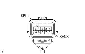
Measure the voltage of the oscillator.

Standard voltage:
Tester Connection Condition Specified Condition
4 (SEL) - Body ground During Active Test Below 1 V
6 (SENS) - Body ground Touch sensor is touched during Active Test Below 1 V
Touch sensor is not touched during Active Test 10 to 14 V


NG

11.CHECK WIRE HARNESS (CERTIFICATION ECU - DOOR ELECTRICAL KEY OSCILLATOR)

OK

REPLACE CERTIFICATION ECU

11.CHECK WIRE HARNESS (CERTIFICATION ECU - DOOR ELECTRICAL KEY OSCILLATOR)
B460031E01
0.083,0.417 0.5,0.667 0.417,0.25 0.25,3.667 0.667,3.917 0.417,0.25 0.74,1.781 0.885,1.438 true 0.896,1.177 0.781,0.792 true 2.021,1.771 2.177,1.417 true 2.594,1.771 2.292,1.427 true 1.813,3.646 2.229,3.229 true 1.938,3.635 2.531,3.646 true 2.438,4.135 1.958,3.781 true 1.01,4.229 1.385,3.802 true 0.094,0.042 1.677,0.313 1.583,0.271 10 false Wire Harness Side: 0.156,0.448 0.635,0.729 0.479,0.281 10 false G29 1.198,0.49 2.781,0.76 1.583,0.271 10 false Certification ECU 0.406,0.677 0.802,0.917 0.396,0.24 10 false SEL1 0.417,1.792 0.875,2.073 0.458,0.281 10 false SEN1 1.656,1.771 2.115,2.052 0.458,0.281 10 false CLG1 2.615,1.75 3.073,2.031 0.458,0.281 10 false CG1B 0.823,2.521 2.646,2.948 1.823,0.427 10 false Door Electrical Key Oscillator (for Driver Side) 2.281,3.115 2.74,3.396 0.458,0.281 10 false SEL 2.594,3.573 3.052,3.854 0.458,0.281 10 false CLGB 2.5,4.104 2.958,4.385 0.458,0.281 10 false CLG 0.625,4.219 1.083,4.5 0.458,0.281 10 false SENS 0.375,3.698 0.833,3.979 0.458,0.281 10 false h2

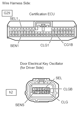
a.

Disconnect the G29 ECU connector.


b.

Disconnect the h2 oscillator connector.


c.

Measure the resistance of the wire harness side connectors.

Standard resistance:
Tester Connection Specified Condition
G29-5 (SEL1) - h2-4 (SEL) Below 1 Ω
G29-22 (SEN1) - h2-6 (SENS)
G29-33 (CLG1) - h2-10 (CLG)
G29-34 (CG1B) - h2-5 (CLGB)
G29-5 (SEL1) or h2-4 (SEL) - Body ground 10 kΩ or higher
G29-22 (SEN1) or h2-6 (SENS) - Body ground
G29-33 (CLG1) or h2-10 (CLG) - Body ground
G29-34 (CG1B) or h2-5 (CLGB) - Body ground


OK

12.CHECK WIRE HARNESS (DOOR ELECTRICAL KEY OSCILLATOR - DOOR ELECTRICAL KEY ANTENNA)

NG

REPAIR OR REPLACE HARNESS OR CONNECTOR

12.CHECK WIRE HARNESS (DOOR ELECTRICAL KEY OSCILLATOR - DOOR ELECTRICAL KEY ANTENNA)
B460030E01
0.5,1.25 0.833,1.5 0.333,0.25 0.5,3.5 0.833,3.75 0.333,0.25 1.719,1.24 2.396,0.833 true 1.563,1.229 1.021,0.927 true 1.292,1.844 1.708,1.396 true 2.313,1.854 1.854,1.396 true 1.854,3.438 2.448,3.438 true 1.875,3.781 2.51,4.219 true 1.031,4.302 1.635,3.802 true 1.021,3.063 1.615,3.458 true 0.083,0.073 1.49,0.333 1.406,0.26 10 false Wire Harness Side: 0.469,0.406 3.427,0.729 2.958,0.323 10 false Door Electrical Key Oscillator (for Driver Side) 2.448,0.74 2.906,0.99 0.458,0.25 10 false ANT1 0.979,1.854 1.438,2.104 0.458,0.25 10 false ANT2 0.688,0.813 1.146,1.063 0.458,0.25 10 false SGT 2.344,1.833 2.802,2.083 0.458,0.25 10 false TRG- 0.583,1.292 1.042,1.542 0.458,0.25 10 false h2 0.594,3.531 1.052,3.781 0.458,0.25 10 false h1 0.479,2.448 3.313,2.865 2.833,0.417 10 false Door Electrical Key Antenna (for Driver Side) 0.656,2.969 1.115,3.219 0.458,0.25 10 false TRG- 2.51,3.344 2.969,3.594 0.458,0.25 10 false ANT2 0.667,4.25 1.125,4.5 0.458,0.25 10 false ANT1 2.563,4.188 3.021,4.438 0.458,0.25 10 false SGT2

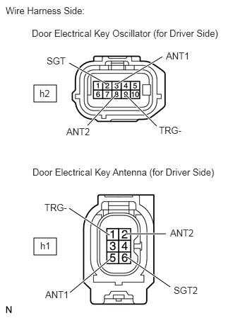
a.

Disconnect the h2 oscillator connector.


b.

Disconnect the h1 antenna connector.


c.

Measure the resistance of the wire harness side connectors.

Standard resistance:
Tester Connection Specified Condition
h2-2 (SGT) - h1-6 (SGT2) Below 1 Ω
h2-3 (ANT1) - h1-5 (ANT1)
h2-8 (ANT2) - h1-2 (ANT2)
h2-9 (TRG-) - h1-1 (TRG-)
h2-2 (SGT) or h1-6 (SGT2) - Body ground 10 kΩ or higher
h2-3 (ANT1) or h1-5 (ANT1) - Body ground
h2-8 (ANT2) or h1-2 (ANT2) - Body ground
h2-9 (TRG-) or h1-1 (TRG-) - Body ground


OK

13.CHECK FRONT DOOR OUTSIDE HANDLE ASSEMBLY (OPERATION)

NG

REPAIR OR REPLACE HARNESS OR CONNECTOR

13.CHECK FRONT DOOR OUTSIDE HANDLE ASSEMBLY (OPERATION)
a.

Temporarily replace the front door outside handle (electrical key antenna) with a new or normally functioning one.


b.

Check that the entry unlock function operates normally (see page Vehicle Interior>DOOR LOCK>SMART ENTRY AND START SYSTEM>OPERATION CHECK).

OK:

Entry unlock function operates normally.


NG

REPLACE DOOR ELECTRICAL KEY OSCILLATOR (for Driver Side)

OK

END (ELECTRICAL KEY ANTENNA IS DEFECTIVE)