DOOR LOCK SMART ENTRY AND START SYSTEM Driver Side Door Entry Lock Function does not Operate
DESCRIPTION
When the touch sensor built into the front door outside handle (for driver side) is turned on, a touch sensor ON signal is transmitted to the certification ECU, and a request signal is then transmitted to both the indoor electrical key oscillator and door electrical key oscillator by the certification ECU. Upon receipt of the request signal, the electrical key transmitter transmits an ID code to the certification ECU. When the certification ECU recognizes that the key is not in the cabin and is outside the vehicle, a door lock signal is transmitted to the main body ECU, causing all the doors to be locked.
WIRING DIAGRAM
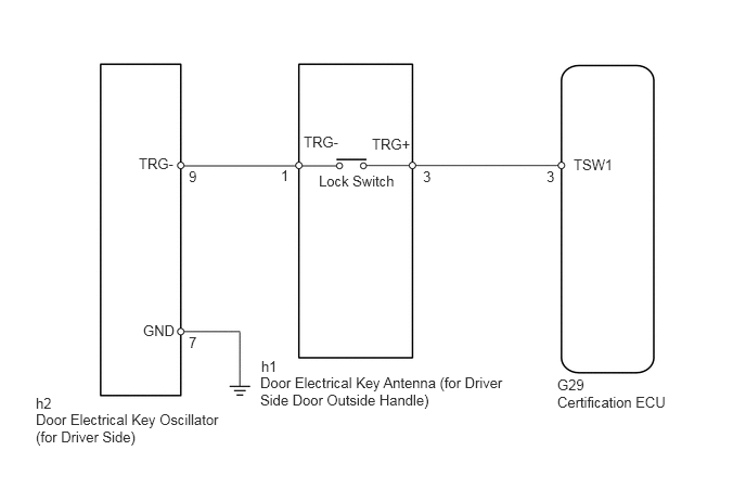
PROCEDURE
Check the driver door entry lock and unlock function operation.
| Condition | Proceed to |
|---|---|
| Driver door entry unlock function operates normally | A |
| Driver door entry lock and unlock functions do not operate | B |
A
B
Connect the intelligent tester to the DLC3.
Turn the ignition switch on (IG) and turn the tester ON.
By following the tester screen display, check whether any DTCs are output.
- Result:
Result Proceed to DTC output (for 2AZ-FE) A DTC output (for 2GR-FE) B No DTC output C
C
A
(See pageEngine / Hybrid System>2AZ-FE STARTING>SMART ENTRY AND START SYSTEM>DIAGNOSTIC TROUBLE CODE CHART)
B
(See pageEngine / Hybrid System>2GR-FE STARTING>SMART ENTRY AND START SYSTEM>DIAGNOSTIC TROUBLE CODE CHART)
Check that all the doors lock when the door control switch (for manual operation) is turned to LOCK.
- OK:
All doors can be lock and unlock with door control switch.
OK
NG
(See pageVehicle Interior>DOOR LOCK>POWER DOOR LOCK CONTROL SYSTEM>HOW TO PROCEED WITH TROUBLESHOOTING)
Check that the wireless door lock and unlock functions operate normally.
- OK:
Wireless door lock and unlock functions operate normally.
OK
NG
Check the Data List for proper functioning of the door lock switch.
| Item | Measurement Item / Range (Display) | Normal Condition | Diagnostic Note |
|---|---|---|---|
| D-Door Trigger Switch | Driver side outside door handle (lock switch) / ON or OFF | ON: Lock switch is pushed
OFF: Lock switch is not pushed |
- |
- OK:
On tester screen, item changes between ON and OFF according to above chart.
OK
NG
Temporarily replace the main body ECU with a new or normally functioning one.
Check that the entry lock and unlock functions operate normally (see page Vehicle Interior>DOOR LOCK>SMART ENTRY AND START SYSTEM>OPERATION CHECK).
- OK:
Entry lock and unlock functions operate normally.
OK
NG
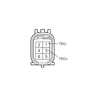
Disconnect the front door outside handle (for driver side) connector.
Measure the resistance between the terminal when the trigger switch is operated.
- Standard resistance:
Tester Connection Condition Specified Condition 1 - 3 Switch released 10 kΩ or higher Switch pressed in Below 1 Ω
OK
NG