RM24M0E
_58
Vehicle Interior
_059568
DOOR LOCK
_0292017
SMART ENTRY AND START SYSTEM
J
DOOR LOCK SMART ENTRY AND START SYSTEM Entry Functions do not Operate at All
DESCRIPTION
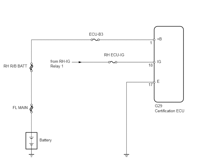
When the entry functions do not operate at all, it is possible that the certification ECU is malfunctioning or that the wire harness leading to the certification ECU is short circuited.
WIRING DIAGRAM
5.469,3.656 6.635,4.042
1.167,0.385
10
false
G29
5.542,1.292 5.844,1.469
0.302,0.177
10
false
+B
3.146,1.125 3.75,1.302
0.604,0.177
10
false
ECU-B3
0.125,2.25 1.073,2.427
0.948,0.177
10
false
RH R/B BATT
0.448,3.719 1.052,3.896
0.604,0.177
10
false
FL MAIN
1.396,4.865 2.292,5.042
0.896,0.177
10
false
Battery
1.781,2.083 2.5,2.458
0.719,0.375
10
false
from RH-IG Relay 1
3.677,1.854 4.51,2.031
0.833,0.177
10
false
RH ECU-IG
5.542,2.094 5.844,2.271
0.302,0.177
10
false
IG
5.292,1.427 5.479,1.604
0.188,0.177
10
false
1
5.24,2.219 5.479,2.396
0.24,0.177
10
false
18
5.24,2.906 5.479,3.083
0.24,0.177
10
false
17
5.542,2.792 5.844,2.969
0.302,0.177
10
false
E
5.469,3.833 6.635,4.219
1.167,0.385
10
false
Certification ECU
PROCEDURE
1.CHECK KEY CANCEL FUNCTION
a.
Check that the key cancel function has been set (see page Vehicle Interior>DOOR LOCK>SMART ENTRY AND START SYSTEM>CUSTOMIZE PARAMETERS).
- OK:
Key cancel function is set.
NG
2.CHECK WIRE HARNESS (CERTIFICATION ECU - BATTERY AND BODY GROUND)
OK
END (UNSET KEY CANCEL FUNCTION)
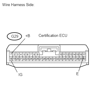
2.CHECK WIRE HARNESS (CERTIFICATION ECU - BATTERY AND BODY GROUND)
2.844,2.583 3.031,2.031
false
0.406,1.938 0.906,1.396
false
0.385,2.167 0.625,2.615
false
0.083,0.083 1.583,0.292
1.5,0.208
10
false
Wire Harness Side:
2.76,2.583 2.917,2.792
0.156,0.208
10
false
E
0.917,1.208 1.125,1.375
0.208,0.167
10
false
+B
0.667,2.615 0.875,2.781
0.208,0.167
10
false
IG
0.406,1.229 0.76,1.427
0.354,0.198
10
false
G29
1.396,1.198 2.5,1.365
1.104,0.167
10
false
Certification ECU
a.
Disconnect the G29 ECU connector.
b.
Measure the resistance of the wire harness side connector.
- Standard resistance:
Tester Connection Specified Condition G29-17 (E) - Body ground Below 1 Ω
c.
Measure the voltage of the wire harness side connector.
- Standard voltage:
Tester Connection Condition Specified Condition G29-18 (IG) - Body ground Ignition switch on (IG) 10 to 14 V Ignition switch off Below 1 V G29-1 (+B) - Body ground Always 10 to 14 V
OK
REPLACE CERTIFICATION ECU
NG
REPAIR OR REPLACE HARNESS OR CONNECTOR