ENGINE HOOD / DOOR SLIDE DOOR REASSEMBLY
CAUTION / NOTICE / HINT
- HINT:
- ·
Use the same procedures for the RH side and LH side.
·The procedures listed below are for the LH side.
·A bolt without a torque specification is shown in the standard bolt chart.
PROCEDURE

 84260J
1.INSTALL POWER SLIDE DOOR SENSOR ASSEMBLY LH (FOR POWER SLIDE DOOR)
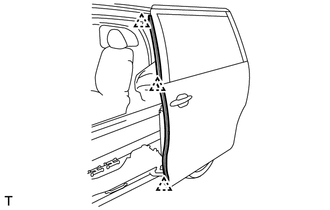
Attach the 3 clips to install the sensor.
68360B
2.INSTALL SLIDE DOOR ROLLER ASSEMBLY LOWER LH
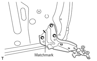
Apply MP grease to the sliding areas of the door check.
Place matchmarks on the door roller and door.
Install the door roller with the 3 bolts.
- Torque:
- 19.5 N*m (199 kgf*cm, 14 ft.*lbf)
68320A
3.INSTALL SLIDE DOOR ROLLER ASSEMBLY LH
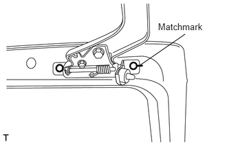
Apply MP grease to the sliding areas of the door check.
Place matchmarks on the door roller and door.
Install the door check to the roller with the 2 bolts.
- Torque:
- 19.5 N*m (199 kgf*cm, 14 ft.*lbf)
69415
4.INSTALL SLIDE DOOR DOWN FEMALE STOPPER
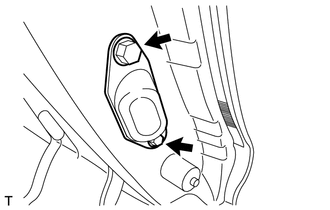
Install the stop with the 2 bolts.
- Torque:
- 7.5 N*m (76 kgf*cm, 67 in.*lbf)
69804
5.INSTALL REAR DOOR WINDOW REGULATOR SUB-ASSEMBLY LH
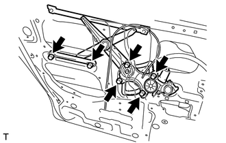
Apply MP grease to the sliding and rotating areas of the window regulator.
- NOTICE:
-
Do not apply grease to the spring of the window regulator.
Install the regulator with the 6 bolts.
- Torque:
- 7.5 N*m (76 kgf*cm, 67 in.*lbf)
69340
6.INSTALL REAR DOOR LOCK ASSEMBLY LH (w/ Power Slide Door)
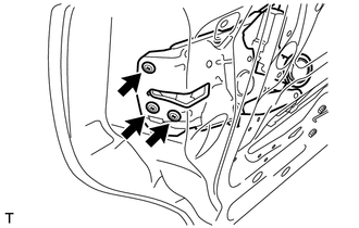
Apply MP grease to the sliding and rotating areas of the lock.
Using a T30 "TORX" socket, install the door lock to the door panel with the 3 screws.
- Torque:
- 8.0 N*m (81 kgf*cm, 70 in.*lbf)
69340
7.INSTALL REAR DOOR LOCK ASSEMBLY LH
Apply MP grease to the sliding and rotating areas of the lock.
Using a T30 "TORX" socket, install the door lock to the door panel with the 3 screws.
- Torque:
- 8.0 N*m (81 kgf*cm, 70 in.*lbf)
69380B
8.INSTALL SLIDE DOOR LOCK ASSEMBLY FRONT LH
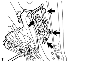
Apply MP grease to the sliding and rotating areas of the lock.
Using a T30 "TORX" socket, install the door lock to the door panel with the 4 screws.
- Torque:
- 7.5 N*m (76 kgf*cm, 67 in.*lbf)
69060
9.INSTALL SLIDE DOOR FULL OPEN STOP LOCK ASSEMBLY LH
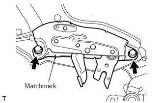
Apply MP grease to the sliding and rotating areas of the lock.
Place matchmarks on the stop lock and roller.
Install the open stop lock with the 2 bolts.
- Torque:
- 19 N*m (194 kgf*cm, 14 ft.*lbf)
Connect the 2 cables.
62346C
10.INSTALL NO. 3 SLIDE DOOR WEATHERSTRIP LH
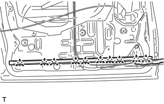
Attach the 10 clips to install the weatherstrip.
69242G
11.INSTALL REAR DOOR OUTSIDE HANDLE PAD REAR
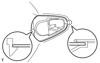
Attach the 2 claws to install the pad.
69241G
12.INSTALL REAR DOOR OUTSIDE HANDLE PAD FRONT
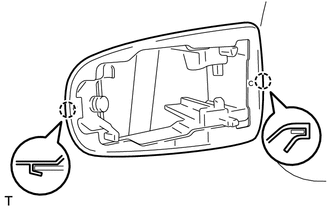
Attach the 2 claws to install the pad.
69204A
13.INSTALL REAR DOOR OUTSIDE HANDLE FRAME SUB-ASSEMBLY LH
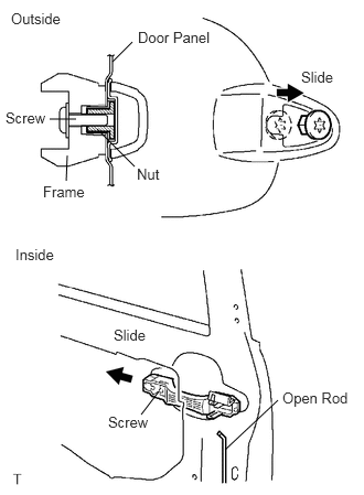
Apply MP grease to the sliding and rotating parts of the outside handle frame.
Slide the outside handle frame in the direction indicated by the arrow in the illustration.
Using a T30 "TORX" socket, install the outside handle frame with the screw.
- Torque:
- 7.0 N*m (71 kgf*cm, 62 in.*lbf)
- NOTICE:
-
Insert a cover between the nut and the door panel.
Install the open rod.
69240
14.INSTALL REAR DOOR OUTSIDE HANDLE ASSEMBLY LH
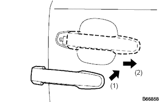
Attach the 4 claws and install the outside handle pad front and rear.
Push the outside handle in the direction indicated by the arrow in the illustration, and install the outside handle.
- NOTICE:
-
If the release plate is not pulled and held when installing the outside handle, it will strike against the outside handle and become damaged.
69227L
15.INSTALL REAR DOOR OUTSIDE HANDLE COVER LH
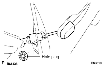
Using a T30 "TORX" socket, install the outside handle cover with the screw.
- Torque:
- 7.0 N*m (71 kgf*cm, 62 in.*lbf)
Install the hole plug.
68104
16.INSTALL REAR DOOR GLASS SUB-ASSEMBLY LH
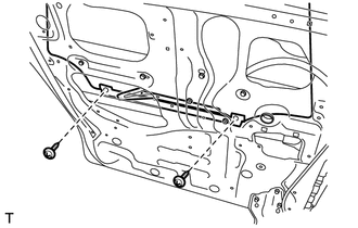
Install the door glass with the 2 bolts.
- Torque:
- 7.5 N*m (76 kgf*cm, 67 in.*lbf)
67408D
17.INSTALL REAR DOOR WINDOW GUIDE SUB-ASSEMBLY REAR LH
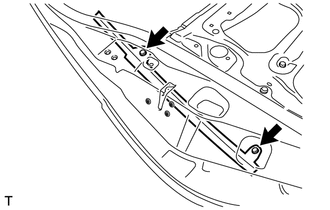
Temporarily install the window frame rear lower with the nut.
Install the window guide with the 2 bolts.
- Torque:
- 7.5 N*m (76 kgf*cm, 67 in.*lbf)
(UPR)
- 5.5 N*m (56 kgf*cm, 49 in.*lbf)
(LWR)
67852A
18.INSTALL NO. 2 SLIDE DOOR SERVICE HOLE COVER
Apply butyl tape to the slide door panel.
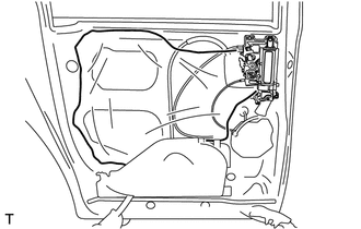
Install a new No. 2 slide door service hole cover.
67522
19.INSTALL SLIDE DOOR PANEL COVER SUB-ASSEMBLY LH
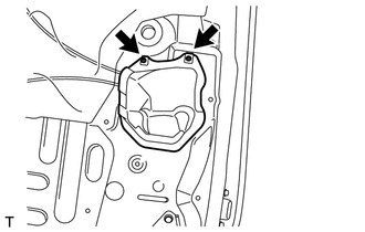
Install the panel cover with the 2 screws.
82154A
20.INSTALL REAR DOOR WIRE LH
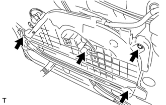
Install the rear door wire with the 4 bolts.
- Torque:
- 7.0 N*m (71 kgf*cm, 62 in.*lbf)
85975C
21.INSTALL SLIDE DOOR CLOSER RELAY (w/ Easy Closer)
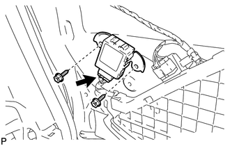
Install the slide door closer relay with the 2 screws.
Connect the connector.
69140
22.INSTALL REAR DOOR LOCK ACTUATOR ASSEMBLY LH
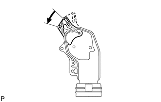
Move the motor lever of the rear door lock actuator assembly LH to the unlock position as shown in the illustration.
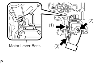
As shown in the illustration, install the motor lever boss of the rear door lock actuator assembly LH to the rear door lock remote control assembly LH.
Install the 3 screws in the order shown in the illustration to install the rear door lock actuator assembly LH.
- NOTICE:
- ·
Move the motor lever of the rear door lock actuator assembly LH to the lock and unlock positions to make sure that the lever moves smoothly and is not stuck.
·If the lever does not move smoothly, slightly loosen the screws and adjust the position of the rear door lock actuator assembly LH by sliding it back and forth.
- HINT:
-
For the slide door lock remote control assembly LH with the earth wire, install the earth wire with the screw (1).
69206C
23.INSTALL REAR DOOR INSIDE HANDLE SUB-ASSEMBLY LH
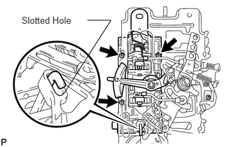
As shown in the illustration, pass the rod of the rear door inside handle sub-assembly LH through the slotted hole of the rear door lock actuator assembly LH.
Install the rear door inside handle sub-assembly LH with the 3 screws.
Connect each rod.
Check the operation of the door inside handle knob.
- NOTICE:
-
Operate the handle knob to the lock and unlock positions. Make sure that the knob operates smoothly and check that it is not sticking or binding.
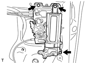
Install the 4 cables.
Install the slide door lock remote control assembly LH with inside handle with the 3 bolts.
- Torque:
- 7.5 N*m (76 kgf*cm, 67 in.*lbf)
75766A
24.INSTALL REAR DOOR WINDOW FRAME MOULDING REAR LH
68164A
25.INSTALL REAR DOOR GLASS WEATHERSTRIP OUTER LH
68152C
26.INSTALL REAR DOOR GLASS RUN LH
69640C
27.INSTALL SLIDE DOOR LOCK REMOTE CONTROL ASSEMBLY LH (w/ Power Slide Door)
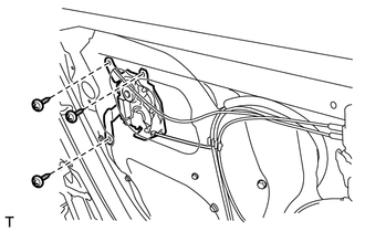
Install the remote control with the 3 bolts.
Connect the connector.
67668A
28.INSTALL SLIDE DOOR WINDOW GARNISH LH
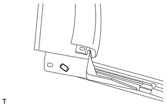
Install the window garnish to the rear door glass weatherstrip inner.
68174A
29.INSTALL REAR DOOR GLASS WEATHERSTRIP INNER LH
Install the door glass weatherstrip to the trim board.
84810D
30.INSTALL REAR POWER WINDOW REGULATOR SWITCH ASSEMBLY
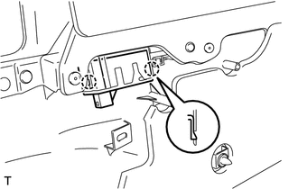
Install the switch.
67604
31.INSTALL REAR DOOR TRIM BOARD SUB ASSEMBLY LH
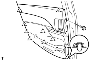
Connect the connector.
Install the trim board.
Using a T25 "TORX" socket, install the screw.