RM24M0E
_52
Drivetrain
_059572
K112 CVT
_0292058
SHIFT LEVER
G
K112 CVT SHIFT LEVER INSPECTION
PROCEDURE

 85903
1.INSPECT SHIFT LOCK CONTROL ECU SUB-ASSEMBLY
1.823,0.906 2.063,0.271
2.063,0.271 2.219,0.271
true
1.115,1.271 0.677,1.271
true
1.188,0.896 0.948,0.26
0.948,0.26 0.865,0.26
true
0.073,0.042 0.271,0.208
0.198,0.167
10
false
*a
0.573,0.177 0.896,0.344
0.323,0.167
10
false
STP
0.5,1.198 0.677,1.365
0.177,0.167
10
false
IG
2.271,0.177 2.448,0.344
0.177,0.167
10
false
E
a.
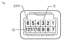
Measure the voltage and resistance according to the value(s) in the table below.
- Standard Voltage and Resistance:
Tester Connection Condition Specified Condition 12 (IG) - 3 (E) Engine switch on (IG) 11 to 14 V Engine switch off Below 1 V 6 (STP) - 3 (E) Brake pedal depressed 11 to 14 V Brake pedal released Below 1 V 3 (E) - Body ground Always Below 1 Ω
| *a | Component with harness connected
(Shift Lock Control ECU) |
- HINT:
- ·
Do not disconnect the shift lock control unit assembly connector.
·If the result is not as specified, replace the shift lock control unit assembly.
2.INSPECT TRANSMISSION CONTROL SWITCH
1.365,2.323 1.365,2.948
true
1.729,2.313 1.729,2.948
true
1.354,1.917 0.458,1.26
true
1.542,1.906 1.542,1.021
1.542,1.021 1.302,1.021
true
1.719,1.906 1.719,1.021
1.719,1.021 2.042,1.021
true
0.292,1.135 0.542,1.313
0.25,0.177
10
false
IG
0.927,0.938 1.427,1.135
0.5,0.198
10
false
SFTU
2.094,0.938 2.542,1.125
0.448,0.188
10
false
SFTD
1.323,2.958 1.51,3.167
0.188,0.208
10
false
S
1.698,2.969 1.906,3.188
0.208,0.219
10
false
E
0.073,0.052 0.458,0.323
0.385,0.271
10
false
*a
a.
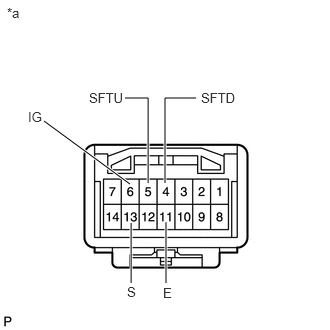
Measure the resistance according to the value(s) in the table below.
- Standard Resistance:
Tester Connection Shift Position Specified Condition 6 (IG) - 13 (S) M, "+" or "-" Below 1 Ω Other than M, "+" or "-" 10 kΩ or higher 5 (SFTU) - 11 (E) "+"
Pressed continuously
(Up shift)Below 1 Ω M 10 kΩ or higher 4 (SFTD) - 11 (E) "-"
Pressed continuously
(Down shift)Below 1 Ω M 10 kΩ or higher
| *a | Component without harness connected
(Transmission Control Switch) |
If the result is not as specified, replace the shift lock control unit.
3.INSPECT SHIFT LOCK SOLENOID
a.
1.333,1.208 0.583,1.583
true
1.594,1.229 1.365,1.625
true
1.833,1.24 2.125,1.615
true
2.094,1.219 2.781,1.594
true
0.063,0.052 0.229,0.208
0.167,0.156
10
false
*a
0.208,1.542 0.583,1.75
0.375,0.208
10
false
SLS+
1.198,1.656 1.594,1.865
0.396,0.208
10
false
SLS-
2.104,1.656 2.333,1.865
0.229,0.208
10
false
E2
2.833,1.563 3.01,1.771
0.177,0.208
10
false
P
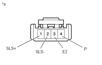
Measure the resistance according to the value(s) in the table below.
- Standard Resistance:
Tester Connection Condition Specified Condition 4 (P) - 3 (E2) Shift lever in P 10 kΩ or higher 4 (P) - 3 (E2) Shift lever not in P Below 1 Ω 2 (SLS-) - 1 (SLS+) Always 112 Ω
| *a | Component without harness connected
(Shift Lock Solenoid) |
If the result is not as specified, replace the shift lock control unit.