HORN HORN RELAY ON-VEHICLE INSPECTION
PROCEDURE

 28800
1.DISCONNECT CABLE FROM NEGATIVE BATTERY TERMINAL
- CAUTION:
-
Wait at least 90 seconds after disconnecting the cable from the negative (-) battery terminal to prevent airbag and seat belt pretensioner activation.
82663A
2.REMOVE ENGINE ROOM NO. 2 RELAY BLOCK COVER
Remove the engine room No. 2 relay block cover.
83650
3.INSPECT FUSE (HORN)
Measure the resistance of the fuse.
- Standard resistance:
Below 1 Ω
If the result is not as specified, replace the fuse.
86530
4.REMOVE HORN RELAY
Remove the horn relay from the engine room No. 2 relay block.
86530
5.INSPECT HORN RELAY
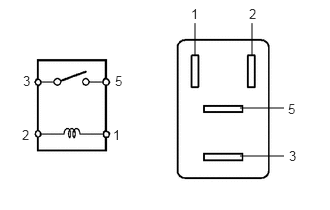
Measure the resistance of the horn relay.
- Standard resistance:
Tester Connection Specified Condition 3 - 5 10 kΩ or higher 3 - 5 Below 1 Ω (when battery voltage is applied to terminals 1 and 2)
If the result is not as specified, replace the relay.
82663A
6.INSTALL ENGINE ROOM NO. 2 RELAY BLOCK COVER
Install the engine room No. 2 relay block cover.
28800
7.CONNECT CABLE TO NEGATIVE BATTERY TERMINAL
28800
8.PERFORM INITIALIZATION
Perform initialization (see page General>INTRODUCTION>REPAIR INSTRUCTION>INITIALIZATION).
- NOTICE:
-
Certain systems need to be initialized after disconnecting and reconnecting the cable from the negative (-) battery terminal.