Home › Engine / Hybrid System › 2GR-FE STARTING › SMART ENTRY AND START SYSTEM › from 2016.05
RM24M0E _51 Engine / Hybrid System _059574 2GR-FE STARTING _0292072 SMART ENTRY AND START SYSTEM J

2GR-FE STARTING  SMART ENTRY AND START SYSTEM  Power Source Mode does not Change to ON (IG and ACC)  


DESCRIPTION

When the engine switch is pushed with the electrical key in the cabin, the main body ECU receives signals to switch the power source mode.

HINT:

To allow use of the intelligent tester to inspect the push-button start function when the engine switch is off, repeat opening and closing any of the doors. Opening and closing a door establishes communication between the intelligent tester and the main body ECU. (Opening and closing a door can also be simulated by operating a door courtesy light switch.)


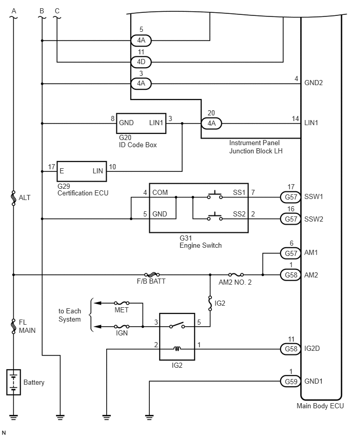
WIRING DIAGRAM
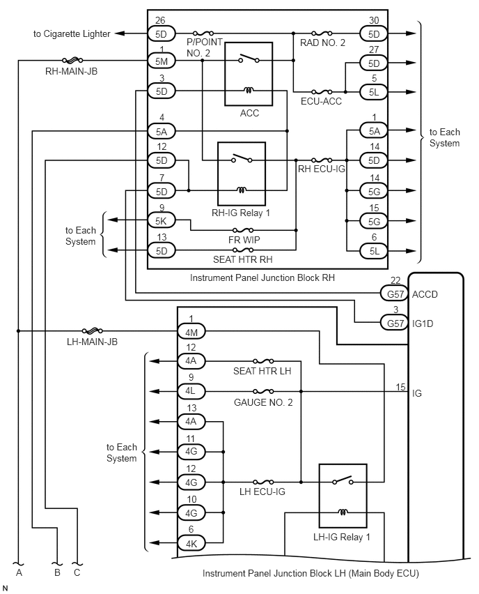
B167171E06
5.51,0.865 5.708,1 0.198,0.135 10 false 5D 5.521,0.656 5.698,0.792 0.177,0.135 10 false 27 5.51,0.427 5.708,0.563 0.198,0.135 10 false 5D 4.49,0.552 5.354,0.688 0.865,0.135 10 false RAD NO. 2 2.792,0.542 3.406,0.896 0.615,0.354 10 false P/POINT NO. 2 0.5,0.417 1.708,0.552 1.208,0.135 10 false to Cigarette Lighter 0.677,0.979 1.5,1.115 0.823,0.135 10 false RH-MAIN-JB 4.5,1.427 5.167,1.563 0.667,0.135 10 false ECU-ACC 6.427,1.885 6.938,2.229 0.51,0.344 10 false to Each System 0.979,3.354 1.49,3.698 0.51,0.344 10 false to Each System 1.594,6.594 2.104,6.938 0.51,0.344 10 false to Each System 0.24,8.469 0.354,8.604 0.115,0.135 10 false A 0.813,8.469 0.927,8.604 0.115,0.135 10 false B 1.104,8.469 1.219,8.604 0.115,0.135 10 false C 1,5.021 1.802,5.167 0.802,0.146 10 false LH-MAIN-JB 3.594,1.604 3.927,1.74 0.333,0.135 10 false ACC 4.458,2.438 5.208,2.573 0.75,0.135 10 false RH ECU-IG 3.167,3.094 4.083,3.229 0.917,0.135 10 false RH-IG Relay 1 3.417,3.5 3.917,3.635 0.5,0.135 10 false FR WIP 3.188,3.792 4.135,3.927 0.948,0.135 10 false SEAT HTR RH 5.521,0.219 5.708,0.354 0.188,0.135 10 false 30 5.521,1.292 5.708,1.427 0.188,0.135 10 false 5L 5.563,1.083 5.656,1.219 0.094,0.135 10 false 5 5.521,1.875 5.719,2.01 0.198,0.135 10 false 5A 5.563,1.667 5.656,1.802 0.094,0.135 10 false 1 5.51,2.313 5.708,2.448 0.198,0.135 10 false 5D 5.531,2.104 5.708,2.24 0.177,0.135 10 false 14 5.51,2.781 5.719,2.917 0.208,0.135 10 false 5G 5.531,2.573 5.708,2.708 0.177,0.135 10 false 14 5.51,3.229 5.719,3.385 0.208,0.156 10 false 5G 5.521,3.021 5.698,3.156 0.177,0.135 10 false 15 5.531,3.667 5.708,3.802 0.177,0.135 10 false 5L 5.563,3.458 5.656,3.594 0.094,0.135 10 false 6 5.792,4.313 6.073,4.469 0.281,0.156 10 false G57 5.844,4.104 6.021,4.24 0.177,0.135 10 false 22 5.792,4.75 6.073,4.885 0.281,0.135 10 false G57 6.167,4.75 6.51,4.885 0.344,0.135 10 false IG1D 6.167,4.313 6.594,4.448 0.427,0.135 10 false ACCD 6.167,5.792 6.354,5.927 0.188,0.135 10 false IG 5.917,5.698 6.104,5.833 0.188,0.135 10 false 15 5.885,4.542 5.979,4.677 0.094,0.135 10 false 3 2.323,0.833 2.531,0.969 0.208,0.135 10 false 5M 2.385,0.656 2.479,0.792 0.094,0.135 10 false 1 2.323,0.427 2.531,0.563 0.208,0.135 10 false 5D 2.323,0.219 2.552,0.354 0.229,0.135 10 false 26 2.333,1.281 2.531,1.417 0.198,0.135 10 false 5D 2.385,1.083 2.479,1.219 0.094,0.135 10 false 3 2.333,1.885 2.531,2.021 0.198,0.135 10 false 5A 2.385,1.667 2.479,1.802 0.094,0.135 10 false 4 2.333,2.313 2.531,2.448 0.198,0.135 10 false 5D 2.344,2.104 2.521,2.24 0.177,0.135 10 false 12 2.333,2.781 2.531,2.917 0.198,0.135 10 false 5D 2.385,2.573 2.479,2.708 0.094,0.135 10 false 7 2.323,3.219 2.531,3.354 0.208,0.135 10 false 5K 2.385,3.021 2.49,3.156 0.104,0.135 10 false 9 2.333,3.667 2.531,3.802 0.198,0.135 10 false 5D 2.344,3.458 2.521,3.594 0.177,0.135 10 false 13 2.771,5.302 2.979,5.438 0.208,0.135 10 false 4A 2.781,5.104 2.958,5.24 0.177,0.135 10 false 12 2.771,4.885 2.979,5.021 0.208,0.135 10 false 4M 2.823,4.677 2.927,4.813 0.104,0.135 10 false 1 2.771,5.75 2.969,5.885 0.198,0.135 10 false 4L 2.823,5.552 2.917,5.688 0.094,0.135 10 false 9 3.49,5.458 4.417,5.656 0.927,0.198 10 false SEAT HTR LH 3.5,5.927 4.667,6.167 1.167,0.24 10 false GAUGE NO. 2 3.583,7.26 4.333,7.479 0.75,0.219 10 false LH ECU-IG 4.688,7.938 5.604,8.177 0.917,0.24 10 false LH-IG Relay 1 3.031,8.479 6.406,8.667 3.375,0.188 10 false Instrument Panel Junction Block LH (Main Body ECU) 2.844,4.063 5.094,4.198 2.25,0.135 10 false Instrument Panel Junction Block RH 2.771,6.208 2.969,6.344 0.198,0.135 10 false 4A 2.792,6.01 2.969,6.146 0.177,0.135 10 false 13 2.771,6.656 2.979,6.792 0.208,0.135 10 false 4G 2.781,6.469 2.958,6.604 0.177,0.135 10 false 11 2.771,7.125 2.979,7.26 0.208,0.135 10 false 4G 2.781,6.917 2.958,7.052 0.177,0.135 10 false 12 2.771,7.583 2.979,7.719 0.208,0.135 10 false 4G 2.792,7.375 2.969,7.51 0.177,0.135 10 false 10 2.781,8.042 2.979,8.177 0.198,0.135 10 false 4K 2.823,7.823 2.917,7.958 0.094,0.135 10 false 6

B168633E03
4.213,2.415 4.406,2.571 0.193,0.156 10 4A 6.178,1.598 6.618,1.754 0.441,0.156 10 GND2 6.178,2.411 6.491,2.567 0.313,0.156 10 LIN1 6.178,3.905 6.593,4.061 0.415,0.156 10 SSW1 6.178,4.363 6.593,4.519 0.415,0.156 10 SSW2 6.178,5.038 6.491,5.194 0.313,0.156 10 AM1 6.178,5.496 6.491,5.652 0.313,0.156 10 AM2 6.178,6.99 6.537,7.146 0.360,0.156 10 IG2D 6.178,7.653 6.584,7.809 0.406,0.156 10 GND1 6.022,8.152 7.053,8.308 1.031,0.156 10 Main Body ECU 4.215,2.206 4.389,2.361 0.173,0.156 10 20 5.782,3.922 6.077,4.078 0.295,0.156 10 G57 4.73,3.823 5.025,3.979 0.295,0.156 10 SS1 4.73,4.256 5.025,4.412 0.295,0.156 10 SS2 3.091,3.823 3.476,3.979 0.385,0.156 10 COM 3.091,4.256 3.441,4.412 0.350,0.156 10 GND 5.832,3.712 6.006,3.868 0.173,0.156 10 17 5.92,2.318 6.093,2.474 0.173,0.156 10 14 5.979,1.509 6.094,1.665 0.114,0.156 10 4 0.97,3.302 1.143,3.458 0.173,0.156 10 17 2.207,3.302 2.402,3.458 0.195,0.156 10 10 5.782,4.363 6.077,4.518 0.295,0.156 10 G57 5.828,4.156 6.011,4.312 0.183,0.156 10 16 5.1,3.823 5.217,3.979 0.118,0.156 10 7 5.1,4.256 5.204,4.412 0.104,0.156 10 2 2.908,3.823 3.026,3.979 0.118,0.156 10 4 2.908,4.256 3.012,4.412 0.104,0.156 10 5 5.782,5.058 6.081,5.214 0.299,0.156 10 G57 5.883,4.857 5.980,5.013 0.097,0.156 10 6 5.782,5.501 6.063,5.657 0.281,0.156 10 G58 5.871,5.294 5.968,5.450 0.097,0.156 10 1 5.782,7 6.070,7.156 0.288,0.156 10 G58 3.487,7.333 3.733,7.489 0.246,0.156 10 IG2 4.003,6.912 4.110,7.068 0.107,0.156 10 1 4.003,6.463 4.103,6.619 0.100,0.156 10 5 4.356,6.076 4.602,6.232 0.246,0.156 10 IG2 4.44,5.645 5.304,5.801 0.864,0.156 10 AM2 NO. 2 3.131,6.463 3.231,6.619 0.100,0.156 10 3 2.354,6.681 2.621,6.837 0.267,0.156 10 IGN 1.188,6.232 1.754,6.588 0.566,0.357 10 to Each System 0.476,7.675 0.945,7.836 0.468,0.161 10 Battery 0.384,6.457 0.777,6.794 0.394,0.337 10 FL MAIN 2.326,6.204 2.648,6.359 0.323,0.156 10 MET 2.778,5.63 3.414,5.786 0.635,0.156 10 F/B BATT 0.381,3.926 0.655,4.082 0.274,0.156 10 ALT 0.236,0.14 0.350,0.296 0.114,0.156 10 A 1.111,0.14 1.253,0.296 0.142,0.156 10 C 0.803,0.14 0.945,0.296 0.142,0.156 10 B 3.131,6.912 3.231,7.068 0.100,0.156 10 2 5.843,6.805 6.016,6.961 0.173,0.156 10 11 5.782,7.667 6.077,7.823 0.295,0.156 10 G59 5.868,7.456 5.972,7.612 0.104,0.156 10 1 2.78,1.164 2.982,1.320 0.202,0.156 10 4D 2.794,0.968 2.968,1.124 0.173,0.156 10 11 2.784,0.725 2.977,0.881 0.193,0.156 10 4A 2.832,0.515 2.931,0.671 0.099,0.156 10 5 2.78,1.605 2.982,1.761 0.202,0.156 10 4A 2.414,2.405 2.741,2.561 0.327,0.156 10 GND 2.414,2.71 2.713,2.866 0.299,0.156 10 G20 2.414,2.85 3.241,3.006 0.827,0.156 10 ID Code Box 4.654,2.816 5.834,3.161 1.180,0.345 10 Instrument Panel Junction Block LH 3.645,4.748 3.944,4.904 0.299,0.156 10 G31 3.645,4.891 4.546,5.047 0.901,0.156 10 Engine Switch 1.165,3.693 1.465,3.849 0.299,0.156 10 G29 1.165,3.833 2.270,3.989 1.105,0.156 10 Certification ECU 3.03,2.405 3.343,2.561 0.313,0.156 10 LIN1 1.209,3.384 1.328,3.539 0.119,0.156 10 E 1.881,3.384 2.139,3.539 0.258,0.156 10 LIN 2.827,1.405 2.935,1.561 0.108,0.156 10 3 3.419,2.32 3.527,2.476 0.108,0.156 10 3 2.25,2.32 2.358,2.476 0.108,0.156 10 8

PROCEDURE

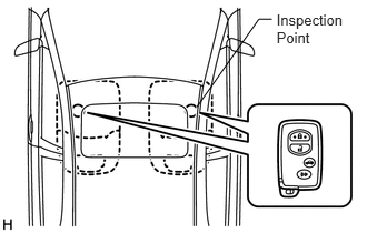
1.CHECK ENTRY FUNCTION DETECTION AREA
a.
B137958E01
2.59,0.1 3.251,0.448 0.661,0.348 10 Inspection Point 1.843,1.005 2.424,0.18 2.424,0.18 2.547,0.18 false

Inspect entry detection area.

i.

When the electrical key is in either of the 2 inspection points in the illustration, the shift lever is in the P position and the brake pedal is depressed, check that the engine switch indicator illuminates in green.

OK:

Engine switch illuminates in green.


HINT:

If the engine switch does not illuminate, perform troubleshooting according to the PROBLEM SYMPTOMS TABLE (See page Vehicle Interior>DOOR LOCK>POWER DOOR LOCK CONTROL SYSTEM>PROBLEM SYMPTOMS TABLE).


OK

2.INSPECT FUSE (AM2 NO. 2 AND F/B BATT)

NG

GO TO OTHER PROBLEM

2.INSPECT FUSE (AM2 NO. 2 AND F/B BATT)
a.

Remove the AM2 No. 2 and F/B BATT fuses from the engine room junction block No. 1.


b.

Measure the resistance of the fuse.

Standard resistance:

Below 1 Ω


OK

3.CHECK CONNECTORS

NG

REPLACE FUSE

3.CHECK CONNECTORS
a.

Check that the connectors are securely connected and the terminals are not deformed or loose.

OK:

The connectors are securely connected and the terminals are not deformed or loose.


OK

4.CHECK HARNESS AND CONNECTOR (MAIN BODY ECU - BATTERY)

NG

REPAIR OR REPLACE CONNECTORS

4.CHECK HARNESS AND CONNECTOR (MAIN BODY ECU - BATTERY)
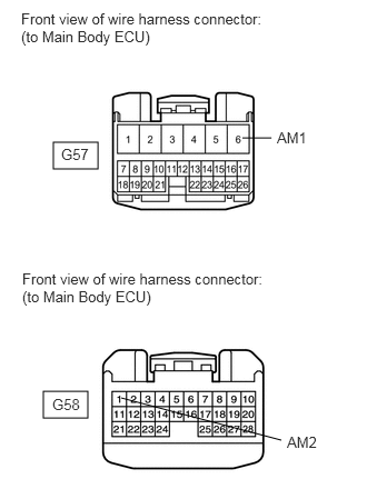
a.
B460086E01
0.5,1.333 0.917,1.583 0.417,0.25 0.406,3.667 0.823,3.917 0.417,0.25 2.271,1.292 2.542,1.292 false 1.135,3.729 2.635,4.125 false 0.198,0.094 2.469,0.625 2.271,0.531 10 false Front view of wire harness connector: (to Main Body ECU) 0.573,1.365 1.406,1.719 0.833,0.354 10 false G57 2.594,1.208 3.167,1.5 0.573,0.292 10 false AM1 2.688,4.063 3.26,4.354 0.573,0.292 10 false AM2 0.49,3.708 1.063,4 0.573,0.292 10 false G58 0.208,2.531 2.469,2.917 2.26,0.385 10 false Front view of wire harness connector: (to Main Body ECU)

Disconnect the G57 and G58 ECU connectors.


b.

Measure the voltage according to the value(s) in the table below.

Standard voltage:
Tester Connection Condition Specified Condition
G57-6 (AM1) - Body ground Always 11 to 14 V
G58-1 (AM2) - Body ground Always 11 to 14 V


OK

5.CHECK HARNESS AND CONNECTOR (MAIN BODY ECU - BODY GROUND)

NG

REPAIR OR REPLACE HARNESS OR CONNECTOR

5.CHECK HARNESS AND CONNECTOR (MAIN BODY ECU - BODY GROUND)
a.

Disconnect the 4A and G59 ECU connectors.
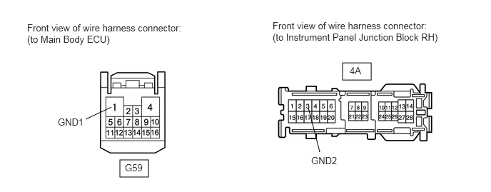
B460087E01
1.75,2.333 2.167,2.583 0.417,0.25 5,0.917 5.417,1.167 0.417,0.25 1.25,1.74 1.625,1.563 false 4.667,2.219 4.5,1.573 false 0.396,0.323 2.667,0.896 2.271,0.573 10 false Front view of wire harness connector: (to Main Body ECU) 0.844,1.698 1.615,2.01 0.771,0.313 10 false GND1 1.823,2.365 2.594,2.677 0.771,0.313 10 false G59 5.104,0.948 5.875,1.26 0.771,0.313 10 false 4A 4.542,2.26 5.313,2.573 0.771,0.313 10 false GND2 3.979,0.292 6.406,0.802 2.427,0.51 10 false Front view of wire harness connector: (to Instrument Panel Junction Block RH)


b.

Measure the resistance according to the value(s) in the table below.

Standard resistance:
Tester Connection (Symbols) Condition Specified Condition
4A-3 (GND2) - Body ground Always Below 1 Ω
G59-1 (GND1) - Body ground Always Below 1 Ω


OK

6.CHECK FOR DTCS

NG

REPAIR OR REPLACE HARNESS OR CONNECTOR

6.CHECK FOR DTCS
a.

Delete the DTCs (See page Engine / Hybrid System>2GR-FE STARTING>SMART ENTRY AND START SYSTEM>DTC CHECK / CLEAR).

HINT:

After all the DTCs are cleared, check if the trouble occurs again 5 seconds after the engine switch is turned on (IG).


b.

Check for DTCs again.

OK:

No DTC is output.


OK

7.READ VALUE USING INTELLIGENT TESTER

NG

7.READ VALUE USING INTELLIGENT TESTER
a.

Connect the intelligent tester to the DLC3.


b.

Turn the engine switch on (IG).


c.

Check the DATA LIST for proper functioning of the start switches 1 and 2.

HINT:

When using the intelligent tester with the engine switch off, turn on and off any of the door courtesy light switches repeatedly at 1.5 second intervals or less until communication between the tester and vehicle starts.


Body:
Tester Display Measurement Item/Range Normal Condition Diagnostic Note
St SW1 Start switch 1/ON or OFF ON: Engine switch is pushed
OFF: Engine switch is not pushed
-
St SW2 Start switch 2/ON or OFF ON: Engine switch is pushed
OFF: Engine switch is not pushed
-

OK:

ON (engine switch is pushed) and OFF (engine switch is not pushed) appear on the screen.


OK

REPLACE INSTRUMENT PANEL JUNCTION BLOCK LH

NG

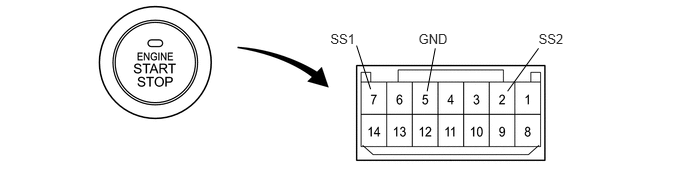
8.INSPECT ENGINE SWITCH
a.

Remove the engine switch.

A109252E18
3.441,0.319 3.749,0.520 0.307,0.201 10 SS1 5.61,0.319 5.915,0.520 0.305,0.201 10 SS2 4.359,0.319 4.834,0.520 0.474,0.201 10 GND 3.714,0.474 3.86,0.929 false 4.534,0.503 4.449,0.95 false 5.61,0.503 5.287,0.95 false


b.

Measure the resistance of the switch.

Standard resistance:
Tester Connection Switch Condition Specified Condition
7 (SS1) - 5 (GND) Pushed Below 1 Ω
2 (SS2) - 5 (GND) Pushed Below 1 Ω
7 (SS1) - 5 (GND) Not pushed 10 kΩ or higher
2 (SS2) - 5 (GND) Not pushed 10 kΩ or higher


OK

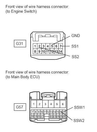
9.CHECK HARNESS AND CONNECTOR (MAIN BODY ECU AND BODY GROUND - ENGINE SWITCH)

NG

9.CHECK HARNESS AND CONNECTOR (MAIN BODY ECU AND BODY GROUND - ENGINE SWITCH)
a.
A393997E01
0.5,1.417 0.917,1.667 0.417,0.25 0.5,3.667 0.917,3.917 0.417,0.25 1.833,1.594 2.479,1.281 false 2.167,1.635 2.469,1.635 false 2.479,1.99 1.396,1.677 false 2.167,3.958 2.563,4.26 false 2.271,3.948 2.583,3.802 false 0.198,0.146 2.479,0.583 2.281,0.438 10 false Front view of wire harness connector: (to Engine Switch) 0.563,1.458 1.146,1.74 0.583,0.281 10 false G31 0.198,2.469 2.448,3 2.25,0.531 10 false Front view of wire harness connector: (to Main Body ECU) 0.563,3.708 1.146,3.99 0.583,0.281 10 false G57 2.531,1.177 3.115,1.458 0.583,0.281 10 false GND 2.531,1.552 3.115,1.833 0.583,0.281 10 false SS1 2.542,1.927 3.125,2.208 0.583,0.281 10 false SS2 2.625,3.719 3.208,4 0.583,0.281 10 false SSW1 2.604,4.188 3.188,4.469 0.583,0.281 10 false SSW2

Measure the resistance according to the value(s) in the table below.

Standard resistance:
Tester Connection Condition Specified Condition
G31-7 (SS1) - G57-17 (SSW1) Always Below 1 Ω
G31-2 (SS2) - G57-16 (SSW2) Always Below 1 Ω
G31-5 (GND) - Body ground Always Below 1 Ω
G31-7 (SS1) or G57-17 (SSW1) - Body ground Always 10 kΩ or higher
G31-2 (SS2) or G57-16 (SSW2) - Body ground Always 10 kΩ or higher


OK

REPLACE INSTRUMENT PANEL JUNCTION BLOCK LH

NG

REPAIR OR REPLACE HARNESS OR CONNECTOR