2GR-FE STARTING SMART ENTRY AND START SYSTEM B2288 Steering Lock Signal Circuit Malfunction
DESCRIPTION
This DTC is output when the main body ECU cannot detect the unlock condition of the steering lock within a specified time.
- HINT:
-
When the main body ECU is replaced with a new one and the negative (-) battery terminal is connected, the power source mode becomes the IG-ON mode. When the battery is removed and reinstalled, the power source mode that was selected when the battery was removed is restored.
-
After the main body ECU is replaced, perform the registration procedures for the engine immobiliser system.
| DTC No. | DTC Detection Condition | Trouble Area |
|---|---|---|
| B2288 | After turning engine switch from off to on (IG), the steering wheel does not unlock for a certain period of time (ECU unlocks steering wheel only when it receives an unlock signal from LIN communication and cable) | ·
Instrument panel junction block LH (Main body ECU) ·
Steering lock ECU ·
Wire harness or connector |
WIRING DIAGRAM
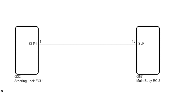
PROCEDURE
Delete the DTCs (See page Engine / Hybrid System>2GR-FE STARTING>SMART ENTRY AND START SYSTEM>DTC CHECK / CLEAR).
After all DTCs are cleared, check if the trouble occurs again 5 seconds after the engine switch is turned on (IG).
Check for DTCs again.
- OK:
DTC B2785 (Communication malfunction between ECUs connected by LIN), DTC B2287 (LIN communication master malfunction) and DTC B2781 (Open/short in steering lock ECU) are not output.
- HINT:
- ·
If DTC B2785 is output (See page Vehicle Interior>ENGINE IMMOBILISER>ENGINE IMMOBILISER SYSTEM>B2785).
·If DTC B2287 is output (See page Engine / Hybrid System>2GR-FE STARTING>SMART ENTRY AND START SYSTEM>B2287).
·If DTC B2271 is output (See page Engine / Hybrid System>2GR-FE STARTING>SMART ENTRY AND START SYSTEM>B2271).
OK
NG
(See pageEngine / Hybrid System>2GR-FE STARTING>SMART ENTRY AND START SYSTEM>DIAGNOSTIC TROUBLE CODE CHART)
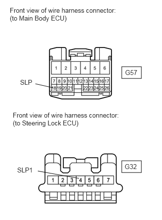
Disconnect the G57 and G32 ECU connectors.
Measure the resistance according to the value(s) in the table below.
- Standard resistance:
Tester Connection Condition Specified Condition G57-18 (SLP) - G32-4 (SLP1) Always Below 1 Ω G57-18 (SLP) or G32-4 (SLP1) - Body ground Always 10 kΩ or higher
OK
NG
After replacing the main body ECU with a normally functioning ECU, check that the steering lock/unlock function operates normally.
- OK:
Steering lock/unlock function operates normally.
- HINT:
-
If steering lock/unlock function does not operate, refer to PROBLEM SYMPTOMS TABLE of the electrical steering lock (steering wheel cannot be unlocked) (See page Steering>STEERING COLUMN>STEERING LOCK SYSTEM>PROBLEM SYMPTOMS TABLE).
OK
NG