2GR-FE STARTING PUSH-BUTTON START Room Oscillator does not Recognize Key
DESCRIPTION
The certification ECU uses the indoor electrical key antenna to send a request signal to the key when: 1) the driver side door is opened and closed, or 2) the engine switch is turned from on (ACC) to off or off to on (ACC). Then, the key transmits its ID code to the door control receiver. The ID code, which is then sent to the certification ECU, is verified by the certification ECU and the verification result is sent to the ID code box. Turning the engine switch from on (ACC) to off stops the engine control system.
The ID code box and the certification ECU communicate encryption codes to each other using the LIN communication line. When the return code from the certification ECU matches the ID code in the memory, the ID code box sends an engine control system start permission signal to the ECM. With the brake pedal depressed, pressing the engine switch starts the engine. With the engine running, pressing the engine switch stops engine.
WIRING DIAGRAM
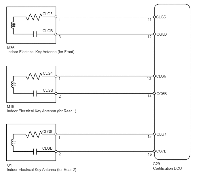
PROCEDURE
Check that the key cancel function has been set (see page Vehicle Interior>DOOR LOCK>SMART ENTRY AND START SYSTEM>CUSTOMIZE PARAMETERS).
- OK:
Key cancel function is set.
NG
OK
Check that the wireless door lock and unlock functions operate normally.
- OK:
Wireless door lock and unlock functions operate normally.
OK
NG
Select the Active Test, use the GTS to generate a control command, and then check that the indoor electrical key antenna (front, rear1, rear2) operates.
| Item | Test Details | Diagnostic Note |
|---|---|---|
| Fr-Seat Inside Transmitter | Indoor electrical key antenna (for front) ON / OFF | - |
| Rr-Seat Inside Transmitter | Indoor electrical key antenna (for rear1) ON / OFF | - |
| Inside Trunk/Backdoor Transmitter | Indoor electrical key antenna (for rear2) ON / OFF | - |
- OK:
When key is brought close to indoor electrical key oscillator, oscillator is turned OFF and indicator on key illuminates.
NG
OK
Disconnect the M36, M19 or O1 antenna connectors.
Disconnect the G29 ECU connector.
Measure the resistance of the wire harness side connectors.
- Standard resistance:
- for Front:
Tester Connection Specified Condition M36-1 (CLG3) - G29-11 (CLG5) Below 1 Ω M36-3 (CLGB) - G29-12 (CG5B) M36-1 (CLG3) or G29-11 (CLG5) - Body ground 10 kΩ or higher M36-3 (CLGB) or G29-12 (CG5B) - Body ground
- for Rear1:
Tester Connection Specified Condition M19-1 (CLG4) - G29-13 (CLG6) Below 1 Ω M19-2 (CLGB) - G29-14 (CG6B) M19-1 (CLG4) or G29-13 (CLG6) - Body ground 10 kΩ or higher M19-2 (CLGB) or G29-14 (CG6B) - Body ground
- for Rear2:
Tester Connection Specified Condition O1-1 (CLG6) - G29-15 (CLG7) Below 1 Ω O1-2 (CLGB) - G29-16 (CG7B) O1-1 (CLG6) or G29-15 (CLG7) - Body ground 10 kΩ or higher O1-2 (CLGB) or G29-16 (CG7B) - Body ground
OK
NG
Carry the key into the vehicle.
Temporarily replace the indoor electrical key oscillator with a new or normally functioning one.
Depress the brake pedal and check that the engine switch indicator illuminates in green.
- OK:
Engine switch indicator illuminates in green.
OK
NG
Remove the key's battery.
While depressing the brake pedal, hold the key near the engine switch. The engine switch's indicator will turn green.
Check that pressing the engine switch starts the engine.
OK
NG
Install the key's battery.
Change the vehicle's location or the key's location. For example, place the key in the vehicle interior near the antenna or door control receiver, etc.). Check the engine start operation.
NG
OK
Temporarily replace the door control transmitter with a new or normally functioning one.
Check that the wireless door lock and unlock functions operate normally.
- OK:
Wireless door lock and unlock functions operate normally.
OK
NG